Deep Climber
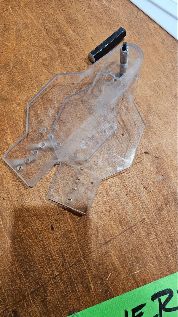
The barb is made up of a few complex polycarbonate parts that are very difficult to machine manually. These can be purchased from vendors or made on a machine capable of making them. Here are the DXFs for teams who wish to use an advanced machine to make them, you will need two bodies and four fingers.
The 02_Deep_Climb_Post had incorrect hole placement for the upper tube plug. It was previously listed as 1.5" from the bottom, that has been changed to 2.5" from the bottom. This shifts everything that was attached at the previous 1.5" height up to the new 2.5" height.
Architecture And Functionality
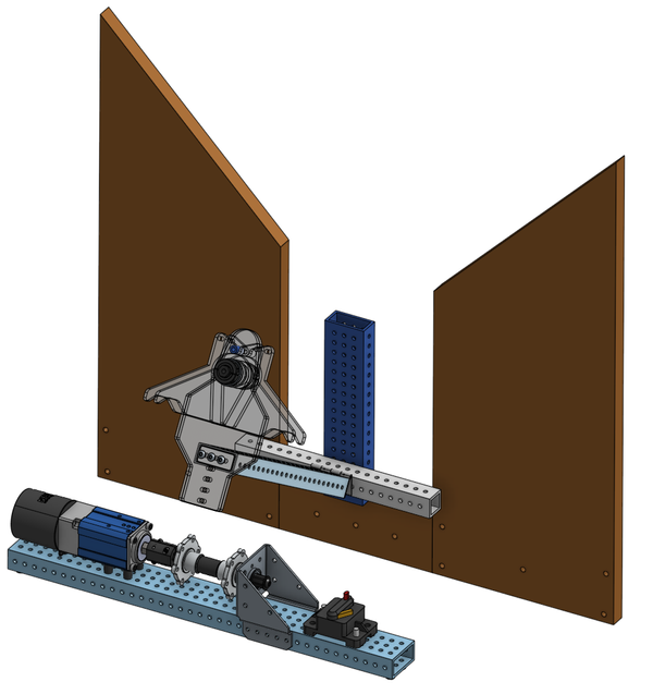
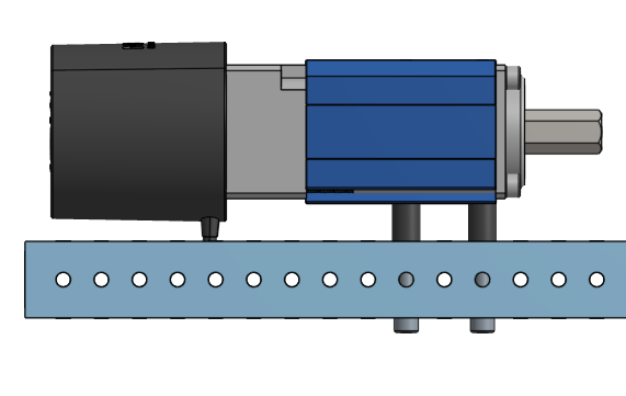
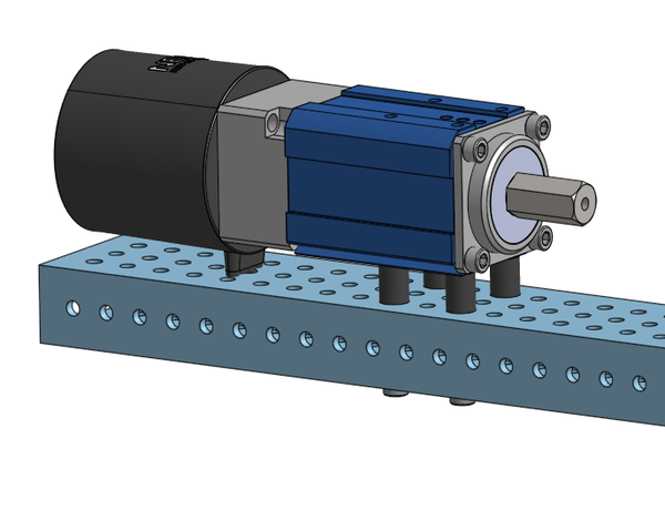
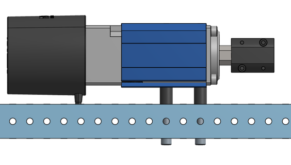
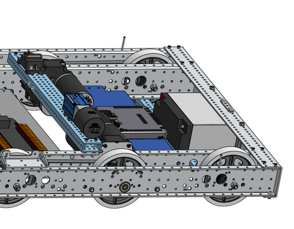
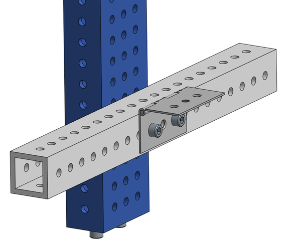
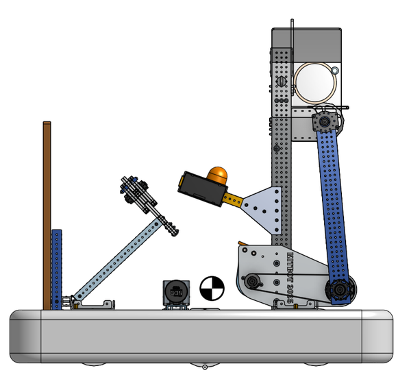
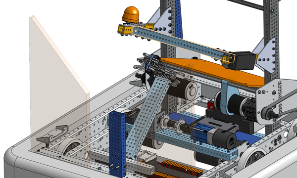
The Everybot Deep Climb mechanism consists of four critical components in the form of the Post, the Barb and the Winch. There is a fourth major component of the climb, the Wall, which is incredibly useful but not needed in order for the climb to work.
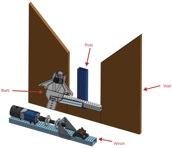
The tube attached to the Barb is passively sprung up such that it will want to be roughly parallel to the post when the Winch is loose.
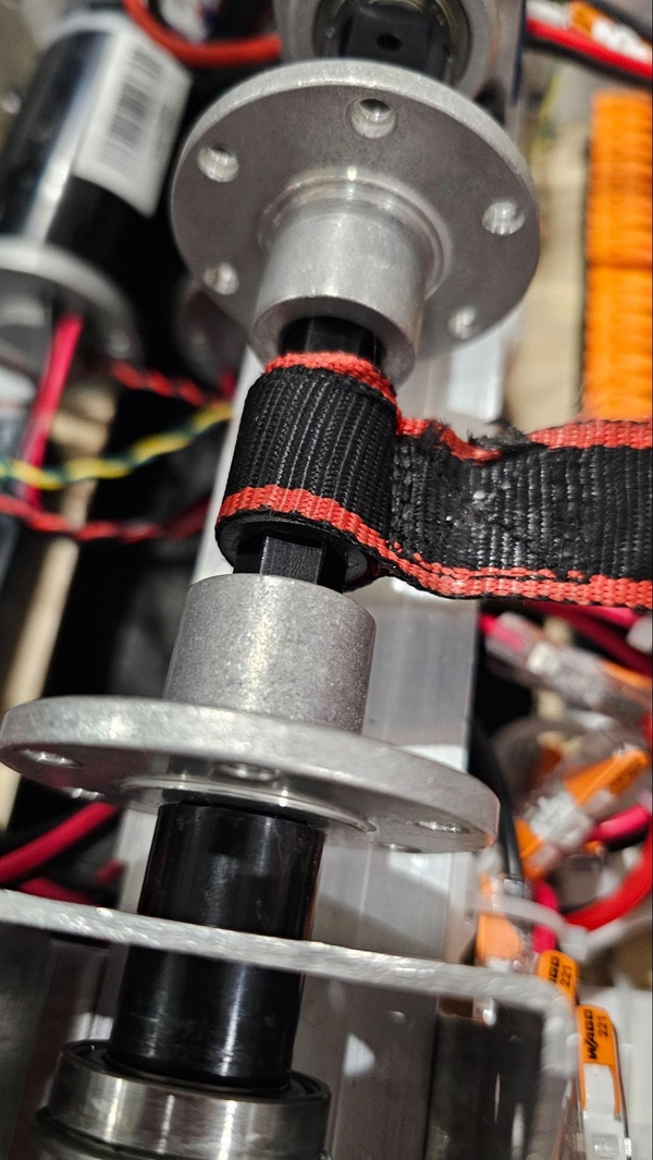
The Barb is connected to the Winch via a ratchet strap which is pulled in by the Winch. As the Winch gives the Barb slack, the Barb will go towards the upright position and when the Winch is wound, it will pull the Barb down towards the Winch.
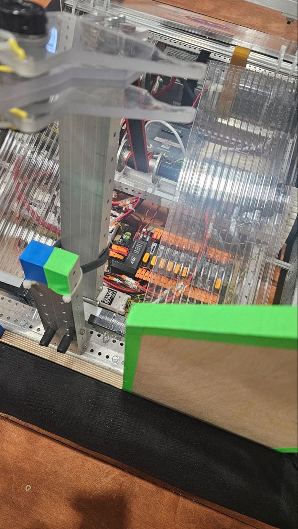
The post has two bolts wrapped in surgical tubing that stick out towards the outside of the robot. In most circumstances, we want the Cage’s bottom to be underneath these bolts when climbing. When catching the Cage under these bolts, we also want to pierce the Cage with the Barb during this time.
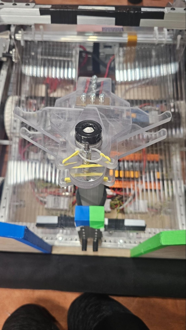
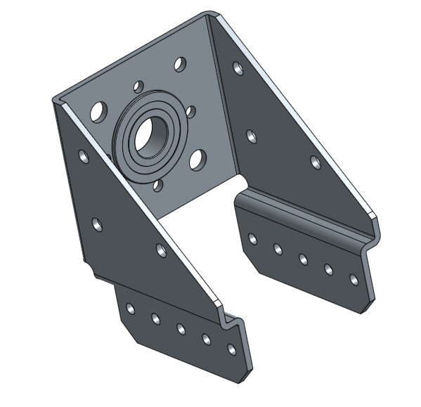
The Barb is designed to enter the Cage with little resistance, then expand such that it is impossible to exit the Cage without human intervention. Thus allowing the robot to climb by securely pulling down on two bars via the groves on the end of the fingers.
With the Barb piercing the Cage and caught under the bolts, the Winch is pulled in until the robot is climbed. If you add any of the other mechanisms to the Everybot you will also need the Cage hard stop. The Cage hard stop prevents being pulled far enough into the robot such that you will risk touching the Chain of the Anchor to the Everybot’s superstructure.
Deep Climb Machining
First start by cutting all of the stock to length:
- You will need two hex shafts, one 5.25” long for the winch and the other 2.75” long for the barb.
- Churros from the drivetrain cut to 3”
- Three 2”x1” box tubes, one 20” long for the 02_Deep_Climb_Winch, one 9” long for the 02_Deep_Climb_Post and finally one 12” long for the 02_Deep_Climb_Barb_Arm.
- One 1”x1” box tube for the 02_Deep_Climb_Reaction_Bar cut to 10” long.
You will also need your ¾” wood but can hold off cutting it until right away.
If you have a patterned box tube, then you can move onto machining the wooden wall. If you need any additional assistance please see the Everybot Evergreens or ask for help in our Discord.
If possible we highly recommend using patterned box tubes, especially for the 2”x1” parts. With that said we understand that patterned tubes are hard to get, so we have tools, in the form of 3D printed jigs, to help address those issues.
Our jigs are designed to be printed in place without supports enabled. There are two versions of the jig, one which is intended for use with drill bushings and the other without. Drill bushing will help you drill more precise holes/straight holes and ensure the jig is very reusable, we recommend purchasing drill bushing if possible.
No Bushing Guide Bushing guide
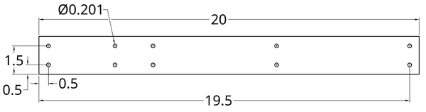
02_Deep_Climb_Winch
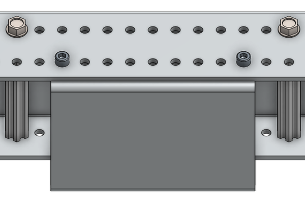
The 02_Deep_Climb_Winch will be made out of a 20” long 2”x1” box tube. This part will be different depending on your gearbox and bearing mount. All holes will be drilled with a #7 to #10 bit or a 13/64 bit (#7 recommended). All of the holes are THRU holes, meaning you drill all the way through the box tube.
Regardless of your setup you will need to drill the following marked holes, two holes 0.5” away from the left and two holes 19.5” away from the left.
If using an AndyMark CIM Sport gearbox you will need to make the following holes.
If using a REV Max Planetary Gearbox you will need to make the following holes.

For the AM Bearing and Motor Mount Bracket, you will need to use these holes on top of the tube.
The Versaframe 2" Wide Versaplanetary Parallel Mount will require several holes on the 1” side of the tube.
Once those holes have been drilled, the part is complete!
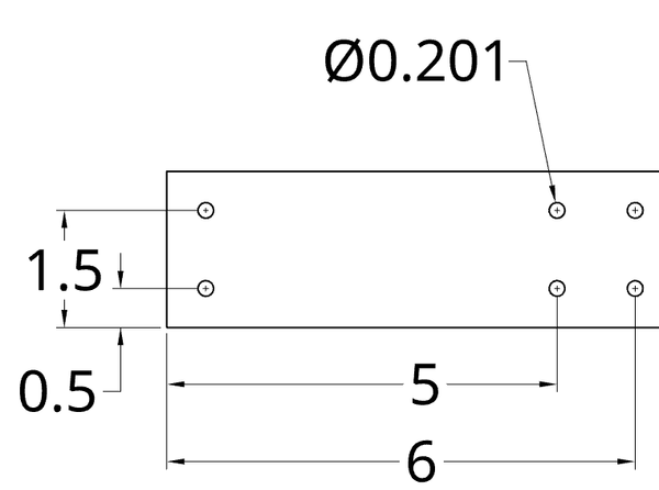
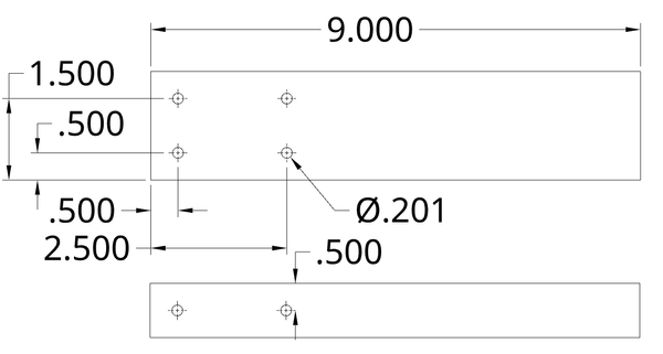
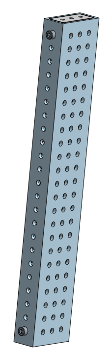
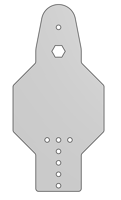
02_Deep_Climb_Post
This part has been updated, ensure that you have holes 2.5" from the bottom instead of 1.5" from the bottom.
You will need a single deep climb post, there will be holes on both the 2” and 1” side to accommodate some tube plugs. You can assume that the holes on the 1” face have the same spacing as the ones on the 2” face.
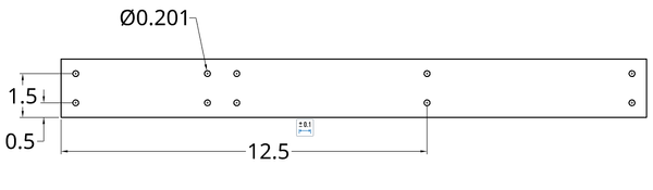
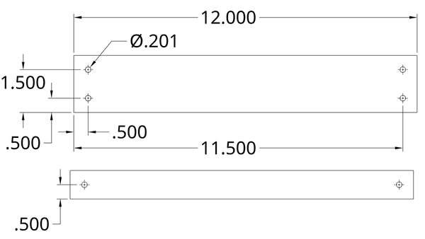
02_Deep_Climb_Barb_Arm
Once again you will need holes on both faces. On the 11.5” it is fine to dimension it off the right end.
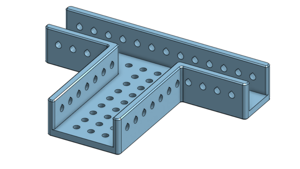
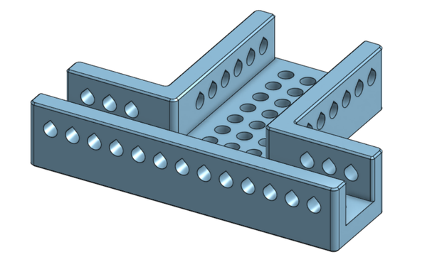
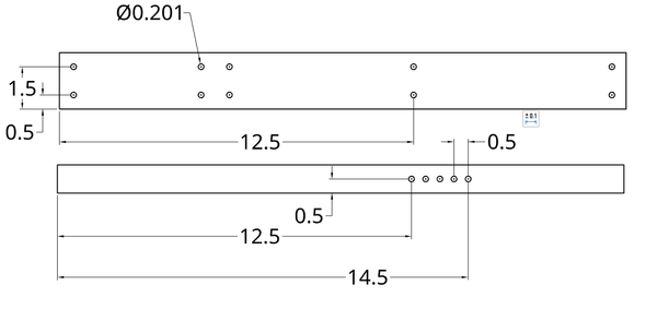
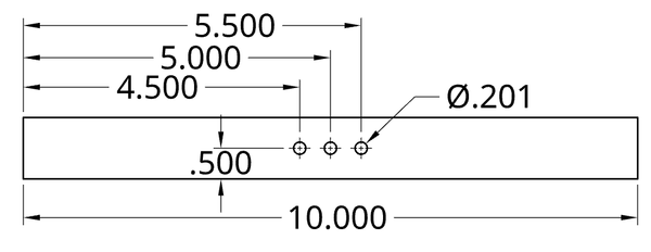
02_Deep_Climb_Reaction_Bar
You will need a single reaction bar made of 1x1. Try your best to center the holes in the middle of the bar but being a bit off center should turn out fine.
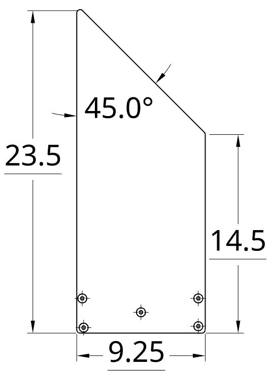
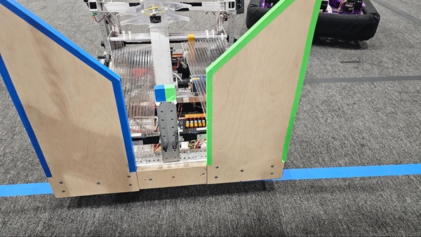
02_Deep_Climb_Wall
You will need to make two walls out of wood. Finding the 45 degree angle can be kind of difficult, so it may be easiest to start with a 23.5” by 9.25” rectangle. Afterwards make a mark at 14.5” and draw a straight line to the corner with a ruler or other straight edge. The holes can be ignored for now. When finished, do your best to sand down the sharp corners and edges to prevent injury.
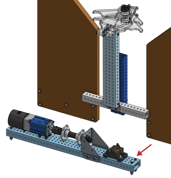
The Winch
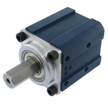
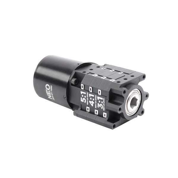
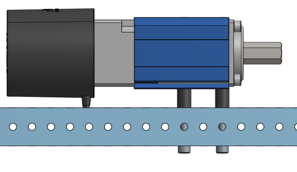
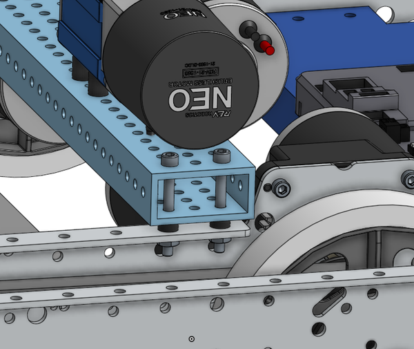
Start by assembling your gearbox of choice, a minimum reduction of 100:1 is required. We recommend either a 100:1 AndyMark CIM Sport or a 100:1 REV Max Planetary gearbox. You will also need your Winch motor, we highly recommend using a brushless motor, like a NEO, here as it has better brake mode performance, which will prevent the Winch from backdriving once the robot is disabled at the end of a match. Please note that the shaft of the Max Planetary will need to be cut down such that it sticks out of the gearbox ~1”.
When you attach your motor, ensure that the leads of the motor will not be facing the box tube when mounted.
Correct Incorrect
If you are using a CIM Sport gearbox you will need to press a pinion onto the shaft of your motor, this is best done with a vice, but can be done with an arbor press. If you have none of these it is possible with a bar clamp but requires extra effort and precision.

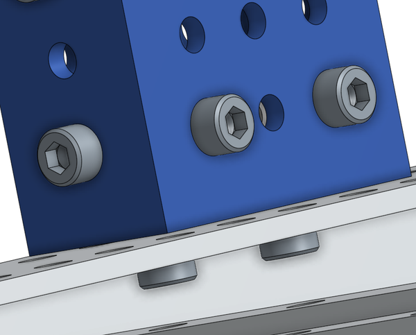
Once your gearbox has been assembled, you will need to attach it to the 02_Winch_Crossmember. This will be done with four 1.75” 10-32 socket head bolts and four 0.5” nylon spacers. The holes closest to the output shaft of the gearbox will be 6” from the end of a wall or in the 12th hole if you have a patterned box tube. There will be a 1” inch offset from the front mounting hole on the CIM Sport and a 2” inch offset for the Max Planetary.
Next you will need to add the shaft support onto the 2x1. Our two recommended brackets are the AM Bearing and Motor Mount Bracket or the Versaframe 2" Wide Versaplanetary Parallel Mount. The Versaframe Mount will have its lower holes 6.5” away from the mounting hole closest to the shaft of the gearbox, using two-four 2.5” 10-32 bolts with Nylock nuts. The AM Bearing Mount will also have its bolts 6.5” away from the mounting hole closest to the shaft of the gearbox, using two 1.5” bolts with Nylock nuts to secure it.
Next add a shaft coupler to the output shaft of your gearbox shaft. You will need to loosen or add bolts to the shaft coupler, this should be done with a 3/32” allen key.
Now you will need to press a bearing into your mount of choice. Make sure that the flange, or raised edge faces away from the gearbox shaft.
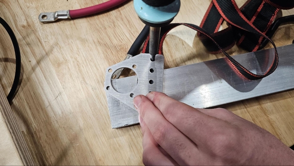
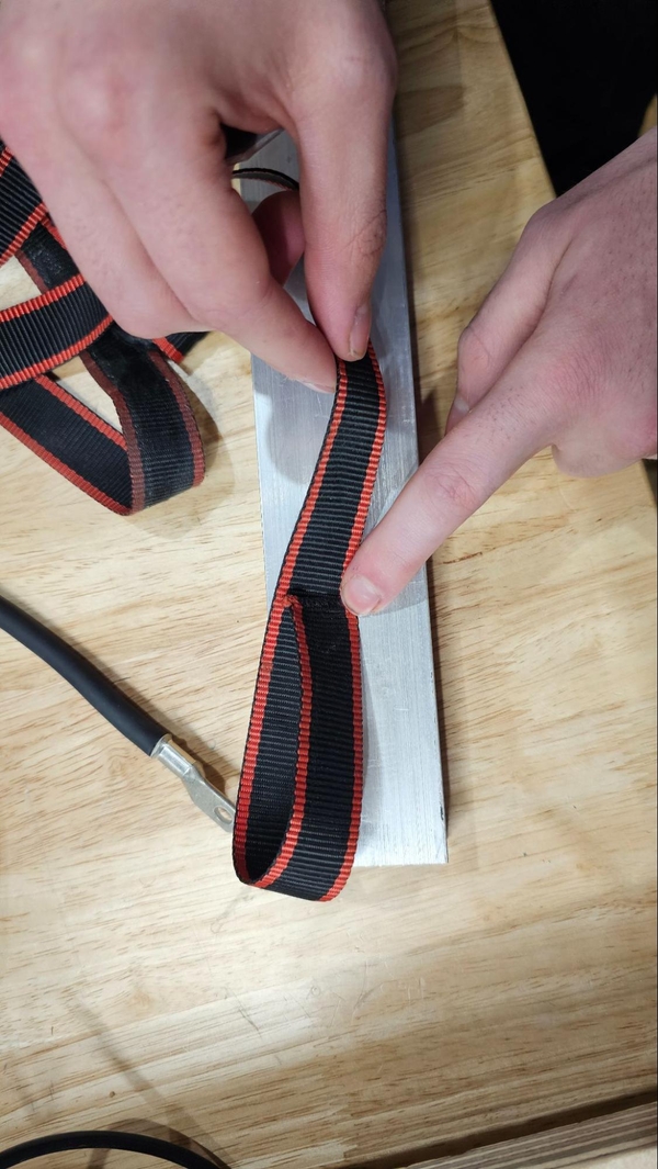
The ratchet strap needs to be prepared. We want to have a loop side of the strap intact, so you will cut material away from a free loop. We cut ours to 32”. Once it has been cut, take the end with nothing on it and folder it over itself. Grab a gusset, or other part, with a 0.5” hole pattern and a soldering iron to make holes for bolts to go through. You will need 4 total holes. Melting the holes is preferred over drilling into the strap. We want to avoid cutting any fibers.
Next insert your shaft through the hex bearing and add the following hardware in order: ⅛” hex spacer, ¼” hex spacer, hex hub, 1” hex spacer with ratchet strap loop around it, hex hub, ¼” spacer. The shaft should then be put into the shaft coupler and the coupler can be tightened.

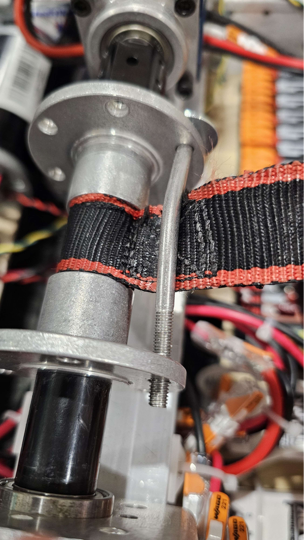
A shaft collar can be affixed onto the end of the hex shaft to prevent the bearing from popping out.

Once the shaft collar is in place, you will need a single ~3” bolt that runs from hub to hub. Fasten with a nylock nut of the correct size, you may also want to add a washer. Please note that the bolt can get very bent, as long as it doesn't collide with anything or come out of it, it is working fine. This is what will allow the rachet strap to spool up around the winch.
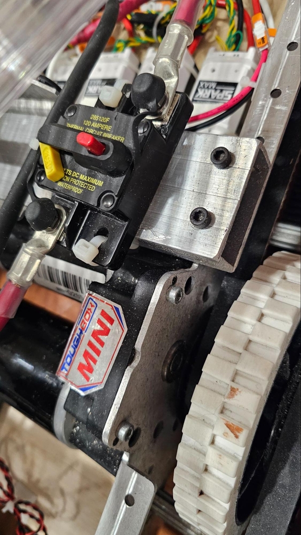
Now would be a fine time to attach the main breaker for the robot. The main breaker can have holes drilled and be mounted with ¼” bolts or zip ties can be used.
The Winch can then be attached to the chassis, using the closest holes to the gearbox in the back of the robot (on the side without the battery). Use 0.25” spacers between the tube and chassis, then affix with 1.75” bolts and Nylock nuts.
Post Assembly
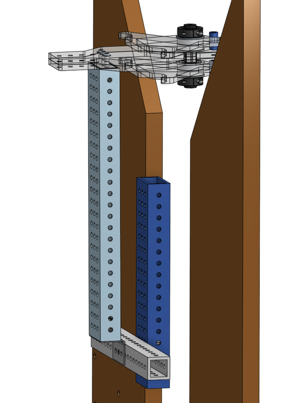
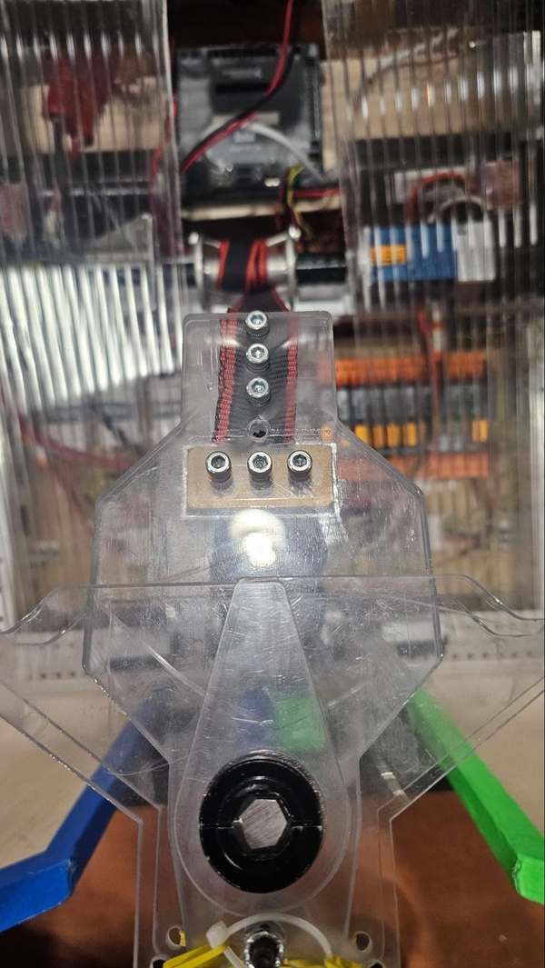
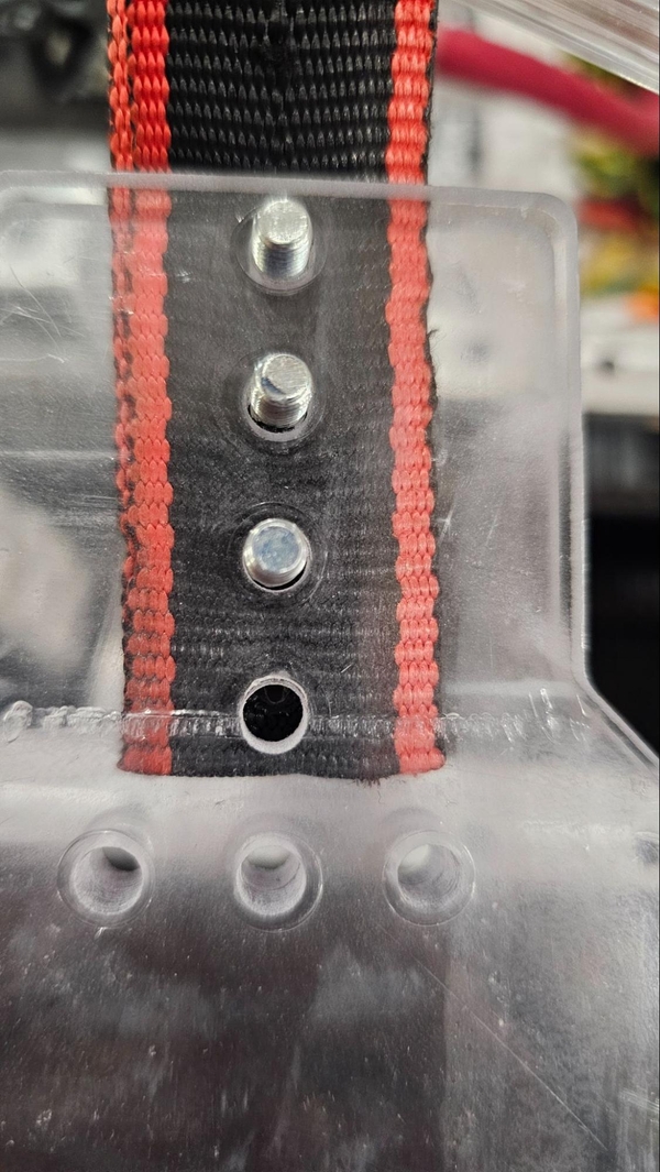
Start by adding tube plugs to the bottom and top of the 02_Deep_Climb_Barb_Arm, which is the 12” long 2”x1” tube. The flat surface of the tube plug should be facing outwards as shown below. Use 0.375” 10-32 bolts on the 1” side of the box tube to secure the tube plugs. We highly recommend using a thread locker to secure the bolts in place. Blue Loctite is a good choice.
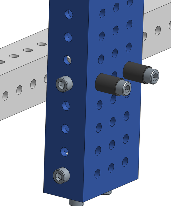
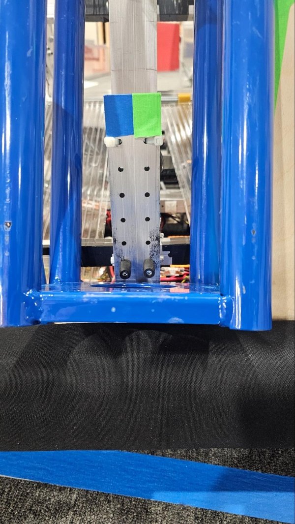
The same can be done for the 9” long 2”x1” 02_Deep_Climb_Post except one tube plug will be located close to the other. The upper tube plug’s side holes will be 2.5” from the bottom or 2” up from the holes on the lower tube plug. Once again use 0.375” 10-32 bolts and use thread locker.
Now we will attach the 02_Deep_Climb_Post to the chassis, it must be centered in the chassis on the outer bolt grid. Use two 10-32 0.5” bolts with threadlocker.
Next grab your hinge and 02_Deep_Cimb_Reaction_Bar. Center the 02_Deep_Cimb_Reaction_Bar with the upper tube plug on the 02_Deep_Climb_Post, then place the hinge in front and add two 1.5” 10-32 bolts, secure with thread locker.
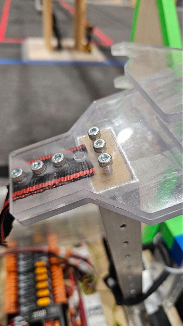
Attach the 02_Deep_Climb_Barb_Arm to the loose flap of the hinge with two 10-32 0.375” bolts with threadlocker.

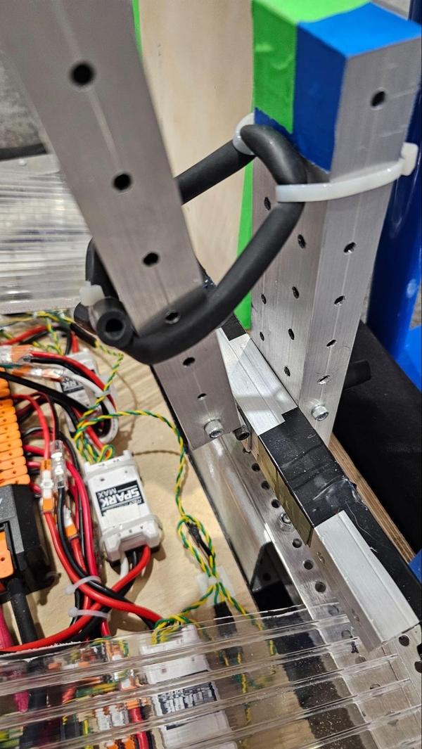
Next, we will add two 0.75” 10-32 bolts with ⅜” spacers on the side of the post that faces outside of the robot. If using plastic spacers, do not use a thread locker that can damage plastic. These bolts will then have surgical tubing placed over these bolts to avoid damaging the Cage.
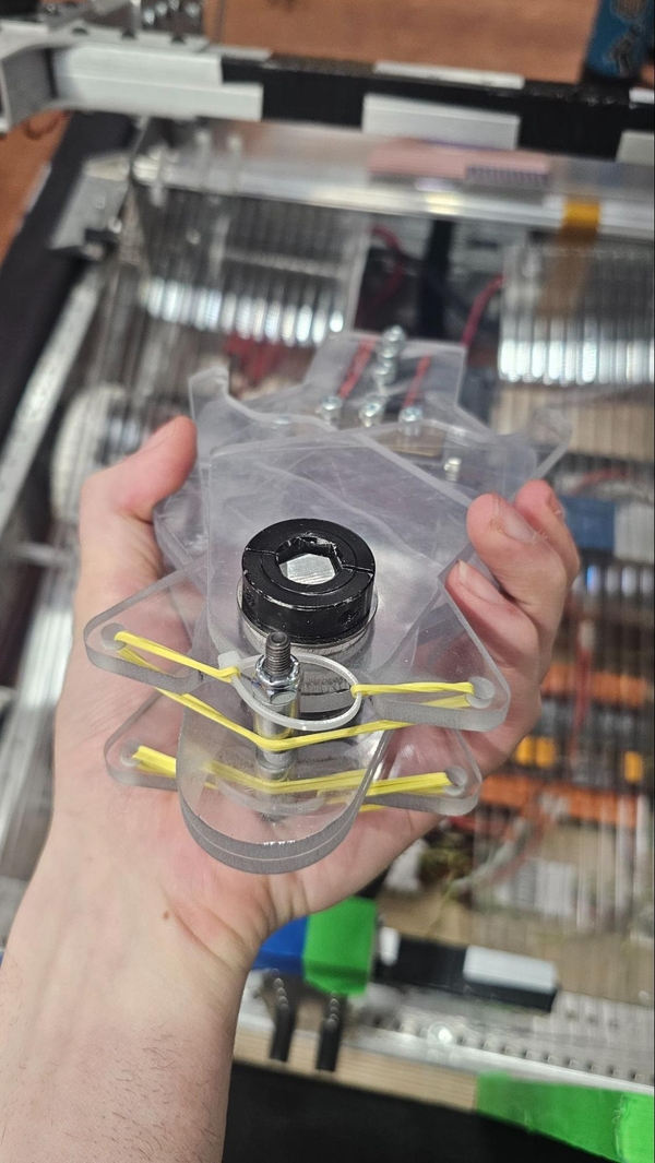
Barb Assembly
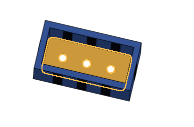
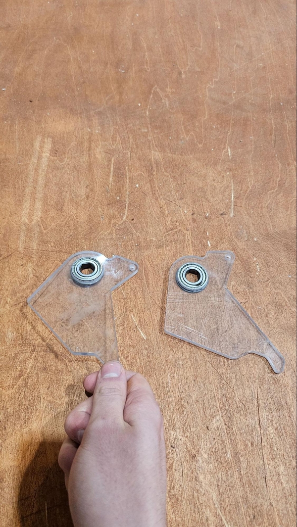
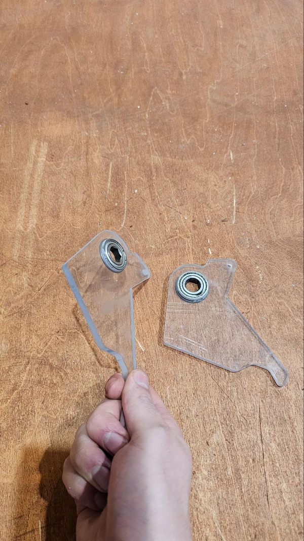
The barb is made up of several polycarbonate parts. These parts are incredibly difficult to make with manual machines. Currently these parts can be purchased from the Thrifty Bot, AndyMark, and SendCutSend. Additionally we recommend that your team reaches out to local teams who may be able to CNC the parts for you, chances are they would be happy to do so!
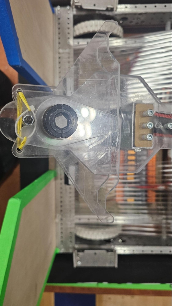
There are 2 different plates, there are 02_Deep_Climb_Fingers and the 02_Deep_Climb_Body.
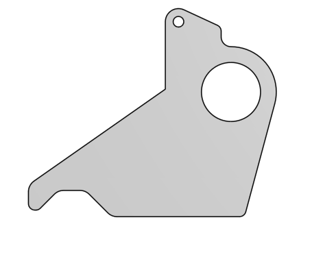
Body Finger
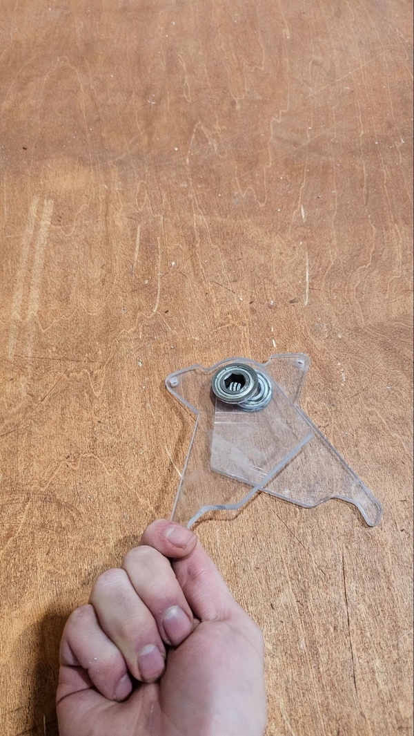
We will first start by stacking the two 02_Deep_Climb_Bodys on top of each other. Then use a ¼” long #10 spacer and a ½” #10 ID spacer on both sides and use a 10-32 2.25” bolt with a Nylock nut to secure it. (the image shows a ¾” spacers, which also works fine but added more parts to the BOM)

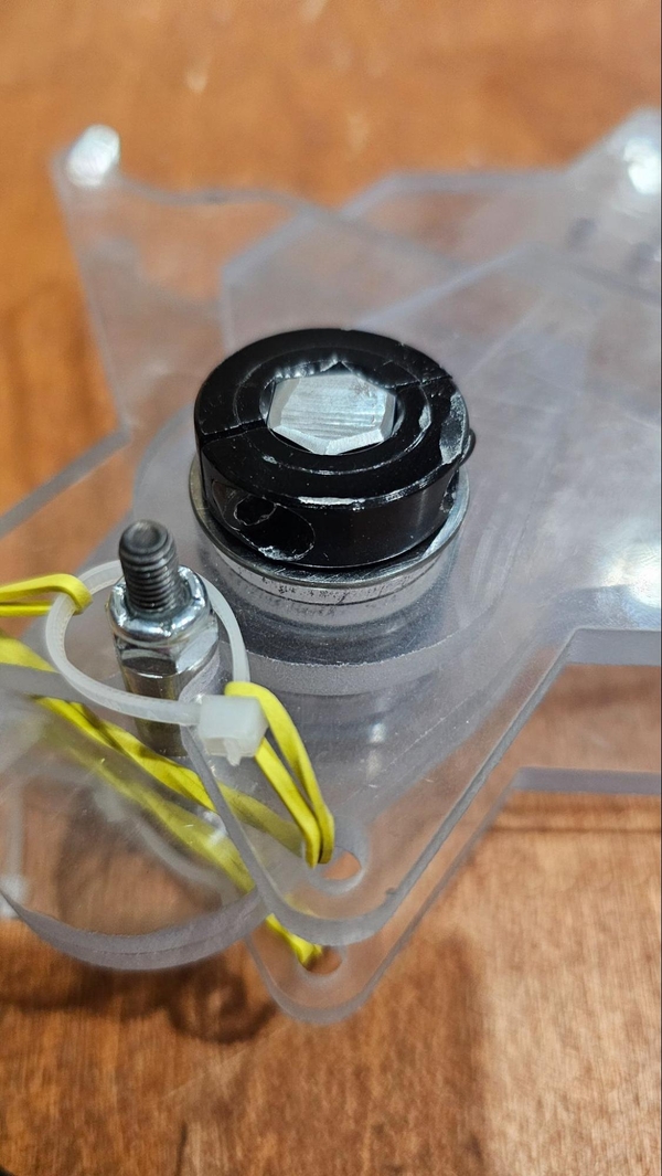
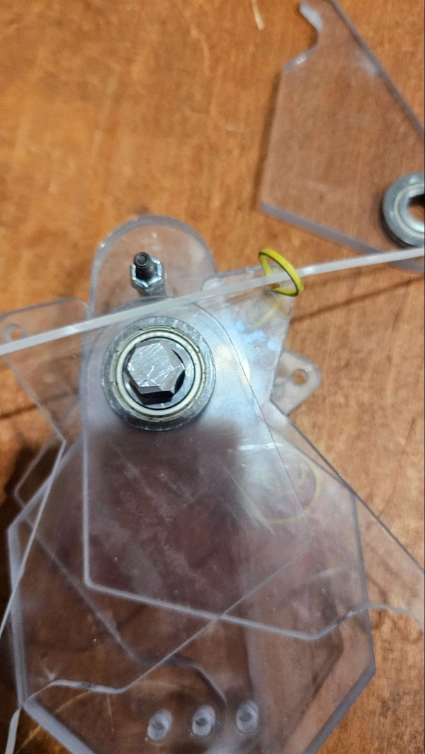
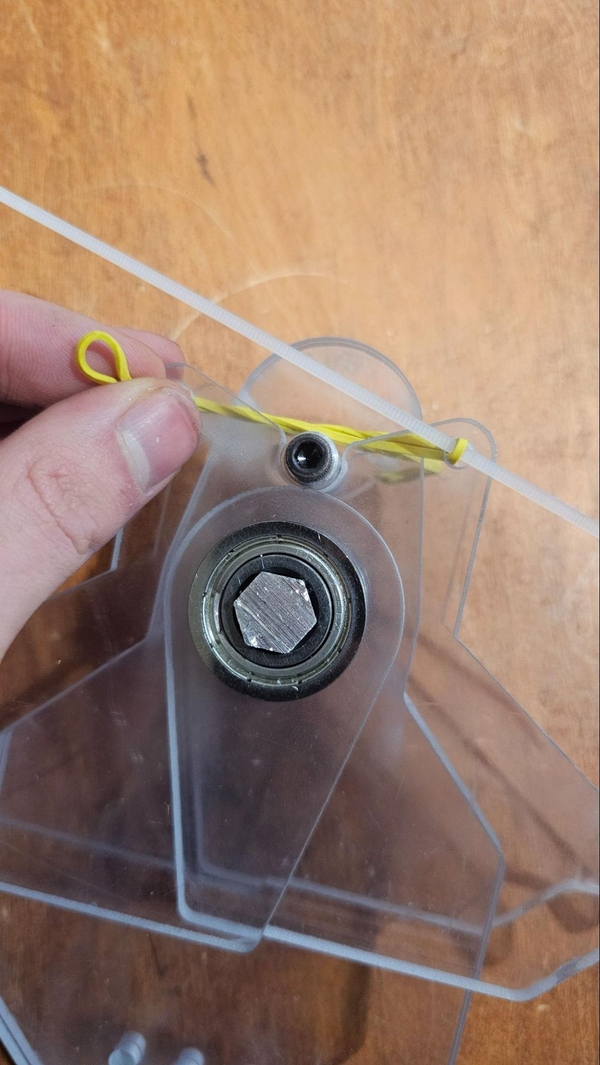
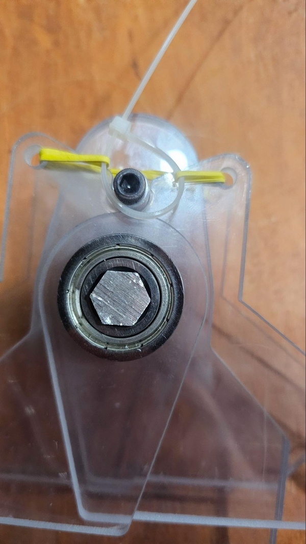
Next you will need to press 1.125” OD hex bearing into the fingers, make sure that all of the bearings are pressed into the same side as shown below. Note the direction of the fingers.
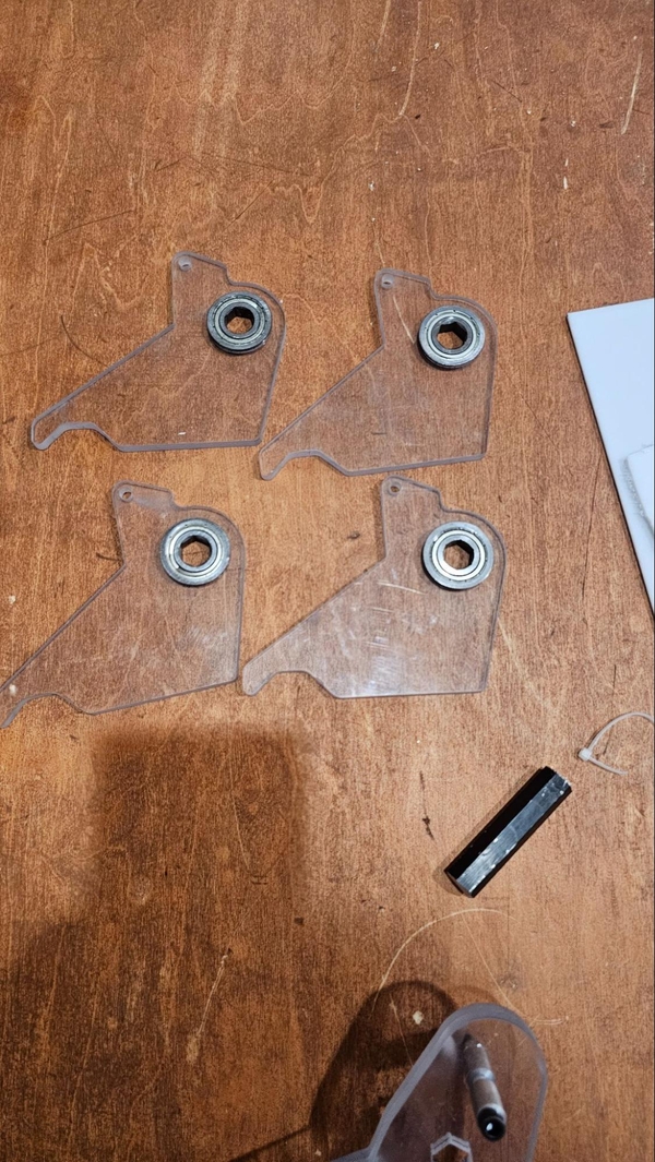
From here you start adding pairs of fingers to the top and bottom of the body via a 2.75” hex shaft. Fingers must be mirrored when stacked, to mirror them properly start with both fingers bearing flange face down on the table.
Put the 2.75” hex shaft through the body and then the fingers. Then repeat with another set of fingers on the other side of the body and prevent the hex shaft from falling out by using a shaft collar on both sides.
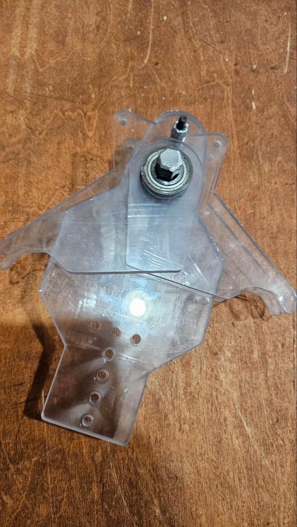
Next comes the passive spring out of the fingers, we will achieve this with zip ties and small rubber bands. Each set of fingers will require a rubber band, starting by fishing a loop through the underside of a finger and sticking a zip tie through it. Then run the rubber band through the hole in the other finger. Zip tie the two together with the zip tie around the bolt. Do this on both sides, taking care to twist the rubber band as little as possible.

Finishing Up The Deep Climb
Start by taking the end of the ratchet strap and slide it in between the two Barb body plates. Use three 10-32 0.75” bolts with Nylock nuts. If you haven’t already added the holes we highly recommend folding the ratchet strap to prevent the bolts from pulling through and shredding the strap.
Next attach the Barb to the top of 02_Deep_Climb_Barb_Arm with three 10-32 0.75” bolts.
DO NOT USE THREADLOCKER ON THESE BOLTS. According to Loctite’s Blue 242 Technical Sheet blue loctite will create stress cracks in thermoplastics like polycarbonate. This will cause the Barb to quickly fail and will render the affected parts useless.
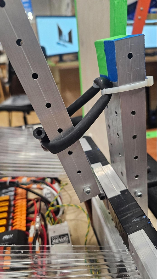
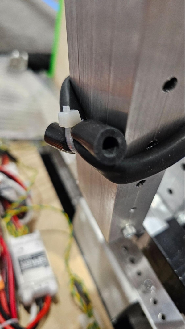
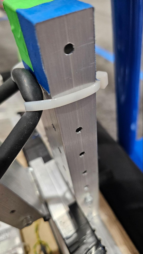
Now that the Barb is attached to both the winch and post assemblies, we can make the 02_Deep_Climb_Barb_Arm passively spring up. To do this we will use two zip ties and some surgical tubing. Pull the 02_Deep_Climb_Barb_Arm up to about parallel with the 02_Deep_Climb_Post and wrap the surgical tubing around the 02_Deep_Climb_Barb_Arm as shown in the rightmost image. Cut it a tad longer and use zip ties to spring up the arm as shown below.
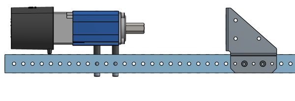
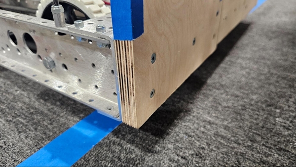
The deep climb support will require the excess material from your chassis end plate and two of the unused churros from assembling your chassis. We will define this as the back of the robot.
After cutting your chassis you will be left with a 4.5” piece, we want to attach it in the center of our robot. It will be attached upside down, with the single hole row side attached underneath the two hole row side of the chassis. Use four 0.5” 10-32 bolts with a Nylock nut on the outer parts of the chassis cutoff to retain it.
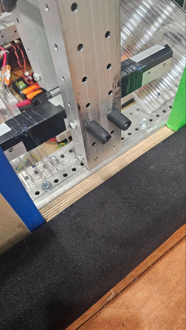
Then cut down two of your unused chassis churros to 3” (3.0625” is better if possible). On the 2nd hole out from where the cutoff is mounted drill a ¼” hole on top and bottom, then use the ¼” Thread Rolling Screws to attach the churro on the top and bottom.
Finally the walls should be lined up with ends of the chassis and slanted such that they will funnel the Cage to the center of the robot. The bolt pattern doesn’t have to match what is shown below but something like that will yield good results. It may be more convenient to add bolts on the outside of the frame rail instead of it like shown in the last image.
Climb Adjustments
The 2025 Everybot Deep Cage climb has built in adjustability to allow maximum compatibility. To understand how to adjust your climb, we must first understand how the climb works.
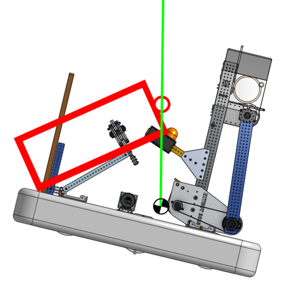
Let’s define Center of Mass or Center of Gravity. On earth, these two terms are interchangeable.
Center of Gravity (CoG or CG): The average, or mean, point of the force of gravity in an object. It is also described as the point where gravity appears to work on an object.

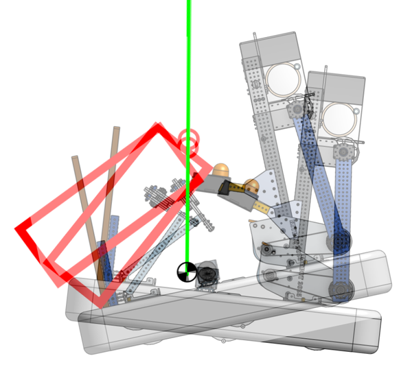
An Everybot with no modifications will have a CG around this location:
Because gravity pulls everything straight down, the CG of the Everybot, by definition, will end up directly below the Chain when climbed.
How the robot reacts at the beginning and the end of the climb will give up valuable information about the location of the CG.
In general, the robot will tilt up before it lifts itself off the ground. The side that tilts up will generally be the opposite side of where the CG is located.
In the following image, the CG is even further forwards than normally expected. When the robot climbs, the robot will tip to have the CG directly below the Chain. Imagine that the Chain was to continue all the way to the ground. The Chain would actually pierce directly through the robot’s CG.
In the next image, the CG has been shifted more towards the rear of the robot.
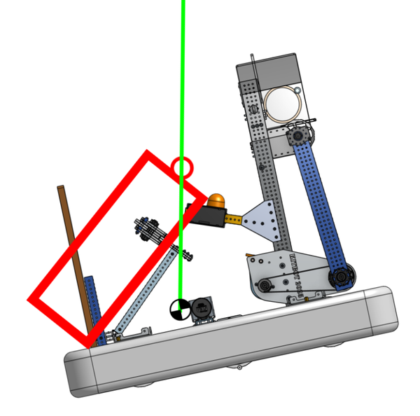
Depending on the final climb angle, you can tell if the CG is towards the front or the rear of the robot.
CAGES NOT DRAWN TO SIZE IN THESE IMAGES.
If the CG is too far to the rear of the robot, the Chain has the opportunity to touch the superstructure up front. This is illegal per G419. “ANCHORS are off-limits. A ROBOT may not contact the ANCHORS. Exceptions are granted for actions that are MOMENTARY and inconsequential.“ Anchors include the Chain and the top surface of the Cage.
We must make sure that the robot does not contact the Chain during a climb. Not only does your climb not count, but it invalidates your whole alliance from receiving the Barge RP.
There are a few ways to do this.
- Add weight to the front of the robot.
- There are pockets to both sides of the battery that could be used to add ballast. Adding Ballast may actually allow the robot to lift further off the ground, creating a larger margin of error, increasing your chances of a successful climb.
- Change the location of the Chain.
- If the Chain at the top of the Cage was to sit further back in the robot, the CG would be pushed forwards in relation to the Chain.
The next two images will have the CG in the same spot, but the Cage location will change.
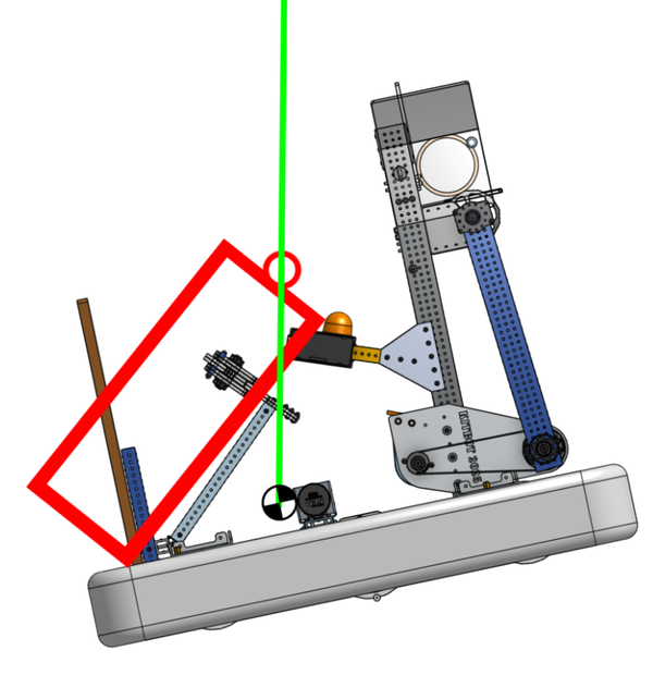
To really drive the point home, here they are overlaid with the Chain in the same place.
The robot’s position will entirely change depending on where the Cage is brought into the robot and held.
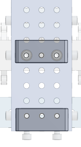
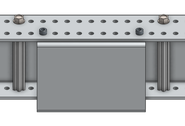
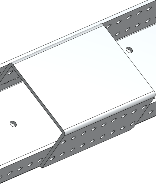
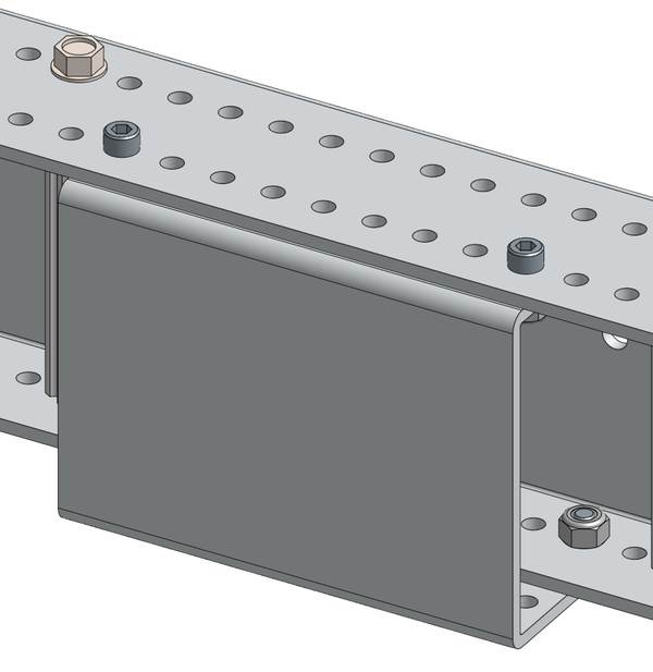
There are two 1x1 tubes that define the Cage Location in the Robot.
The lower 1x1:
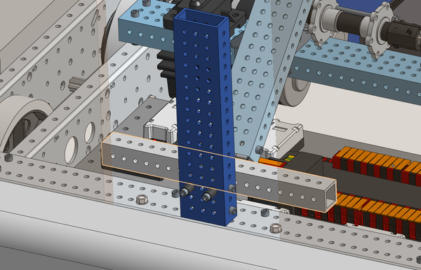
The upper 1x1:
By moving these around, you can control the location of the Cage inside of your robot.
For example, if the robot’s CG is too far forwards, you may need to move the hardstop down and towards the front of the robot. If the CG is too far to the rear, it may need the lower bar to move up.
We encourage you to move these surfaces around to best fit the needs of your robot.
Since we cannot possibly cover all scenarios in this manual, you may find yourself in a situation where the climb is not successful that has not been discussed. Please feel free to reach out to us via our Discord!