Everybot Electrical
The Everybot electrical system can be wired using wire and connectors included in the Kit of Parts, with the electrical components coming in the Rookie Kit of Parts or retained from previous seasons for non-rookies. One additional Spark Max or other motor controllers are necessary to power the Everybot seven motors. The electrical system can be wired using whatever legal combination of newer REV and CTRE control system components your team has. Rookie teams receive a full system of the newer REV control system components which this guide will primarily focus on because it is assumed that teams with other control systems may have some experience with FRC wiring.
How to Wire a Robot video from FIRST
For more visual aid we highly recommend watching this video. Wiring a battery, main breaker, motor controllers, the roboRIO, RSL (Robot Signal Light) and CAN bus is covered.
Introduction to FRC Robot Wiring
Above we linked a WPILIB resource that we highly recommend looking at for some additional information.
For more tips on navigating this resource please the Everybot Evergreens electrical section.
Bellypan
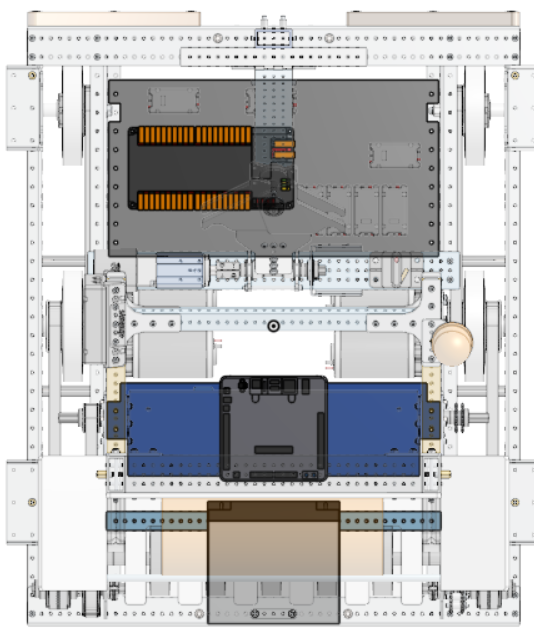
We used two separate bellypans made from wood, either thickness of wood will work. The bellypan closer to the climb hosts the PDH and Spark Maxes. The bellypan closer to the battery/intake hosts the roborio. The radio/RSL are on the superstructure and main breaker is on the climber winch 2x1.
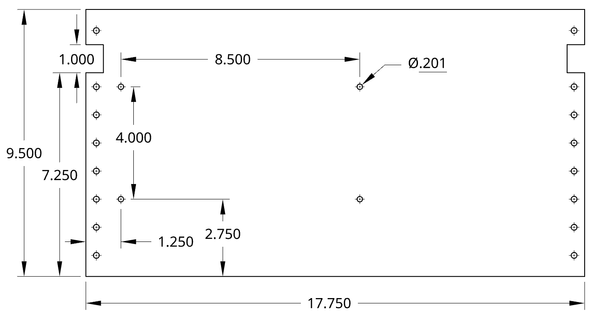
Neither of the bellypans have to be incredibly accurate or mirror what we have done. A 17.75” width will allow for a little bit of room on the sides when placing it into your chassis, as long as it is under 18” it should fit nicely. The mounting holes can be drilled after it is attached to the robot. Finally the 4 dimensioned holes in the center are for the PDH, these can be carefully drilled with a smaller drill bit using the PDH as a guide or the holes can be marked before it is mounted. Make sure to have a cutout as the bolts from the wheels on the chassis will need to be accounted for.
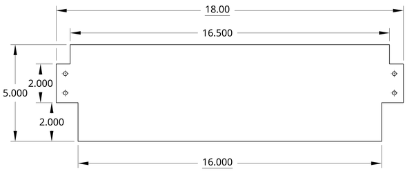
Here we would recommend having the longest width slightly under 18” so it can nicely fit between the rails. The depth is a bit low to allow for plenty of room when removing the battery and the side cutouts are for churro bolts and the robot’s superstructure.
Using Wagos
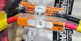
Whenever we need to connect a motor controller to a motor or when we need to extend power wires for the motor controllers, we use Wagos, specifically 221-2401 inline Wagos. These Wagos are good for wires up to 12 AWG, some motors, like the Kraken, will desire larger gauge wires, for those we would recommend a 221-600 model that can handle up to 10 AWG. The 221-613 can be purchased at Home Depot. Using the 221-2401 with Krakens will cause the housing to melt.
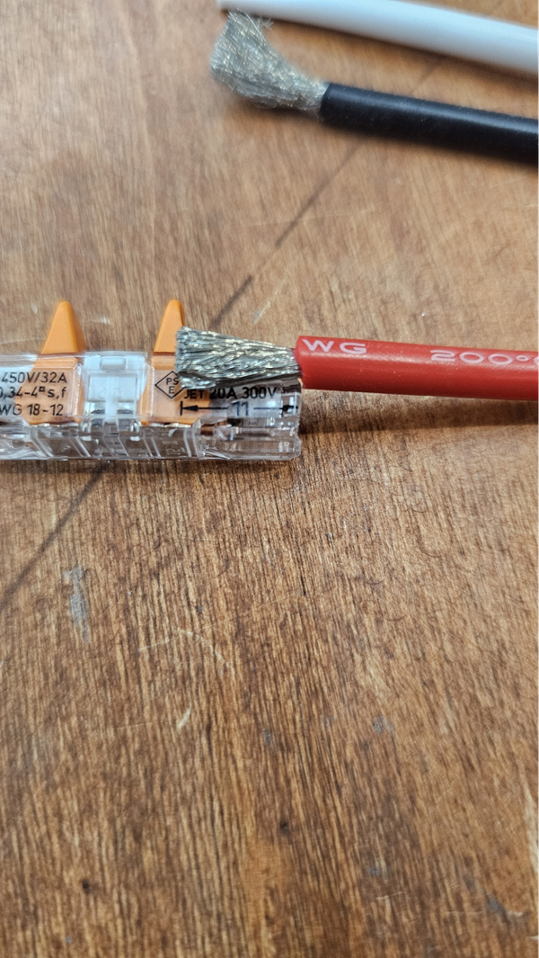
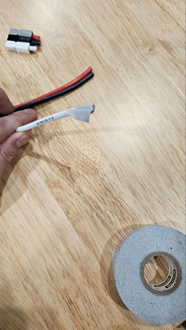
Wagos are very user friendly and decently simple to use. Start by stripping wire to 11mm, which is nicely displayed on the side of Wago. Below shows a decent length of stripped wire.
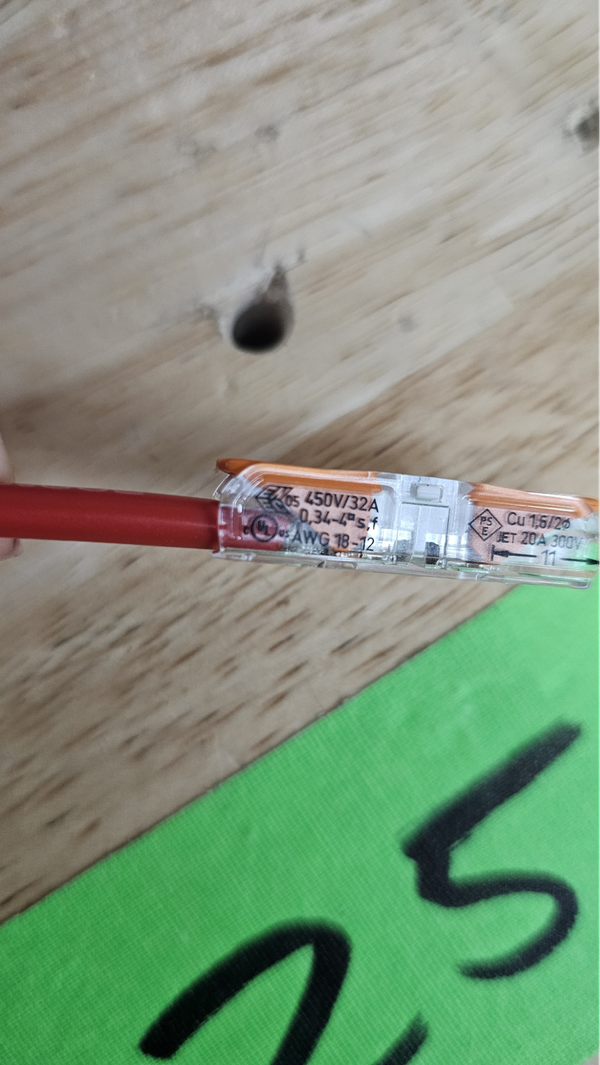
Once stripped, open the Wago, push the wire against the end and close the gate onto the wire. You should be able to give the wire a small tug on the wire without the wire coming out.
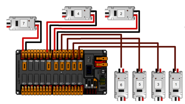
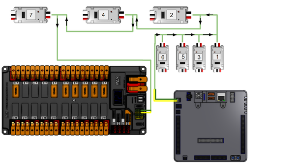
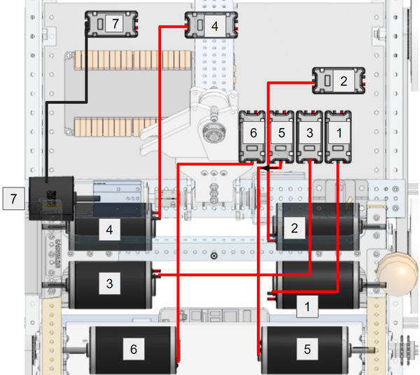
Here is the power wiring diagram for the motor controllers. We ran out of room for 6, 5, 3 and 1 so we represented both wires with a single one. Assume they are wired like the upper motors in the diagram. It does not matter what slot on the PDH the motor is plugged into, use what is most convenient and ensure that the slot has a 40A breaker. 12 AWG wire should be used to extend any electrical connections when needed here.
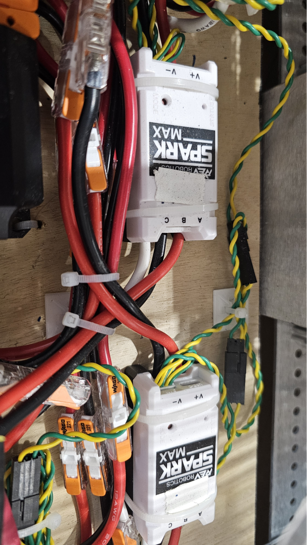
The Spark Maxes can be held down via VHB, velcro or zip ties. We chose to use zip ties.

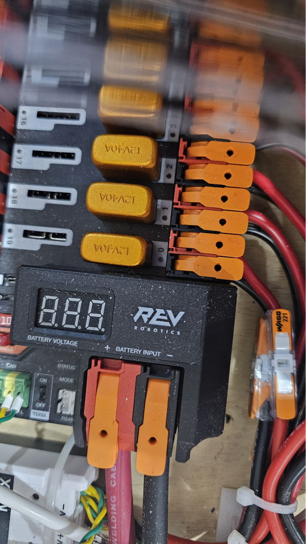
It is good practice to cover any unused PDH slots with electrical tape to prevent metal shavings or debris from getting inside.
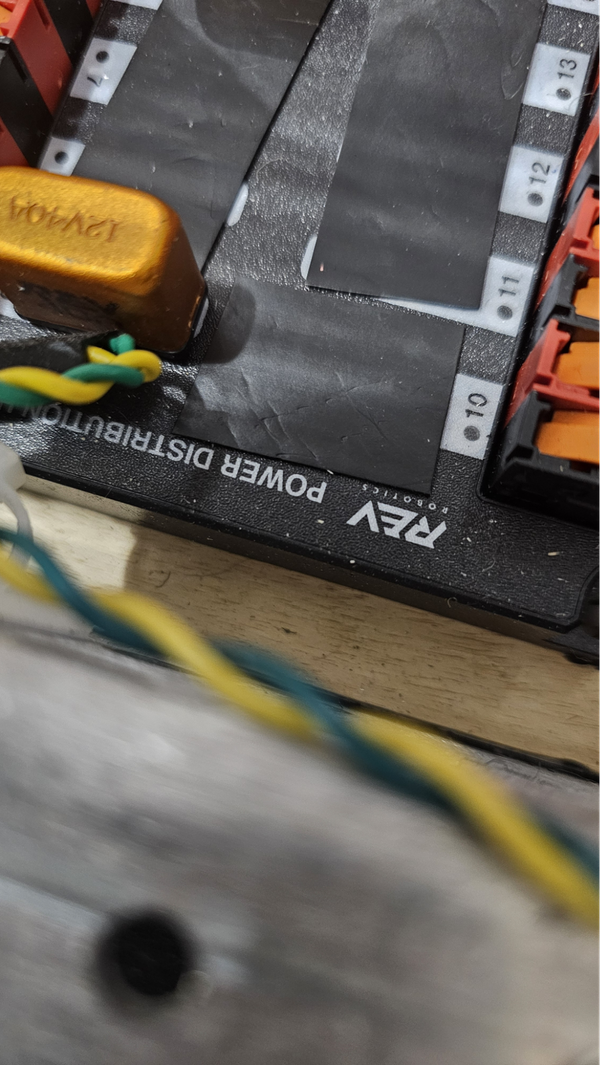
Good robot discipline dictates that you should frequently vacuum out the robot and never drill over the electronics without sufficient coverings. Above is a bad example, the PDH is more dirty than it should be.
This is how the CAN Bus is wired, the CAN chain starts in the roborio and terminates in the PDH. The CAN chain goes from device to device, make sure you have no loops.
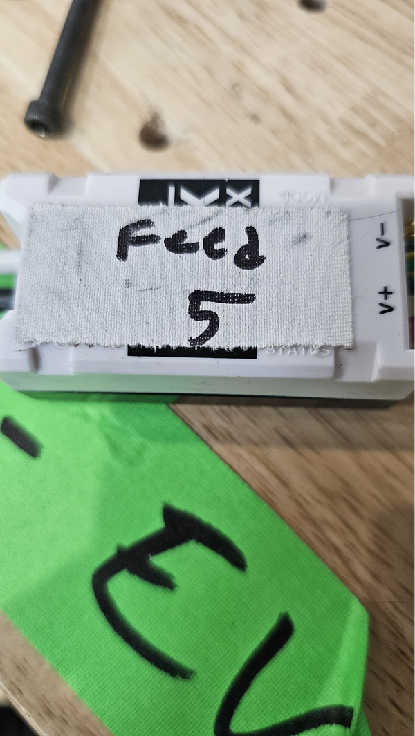
At this time we would recommend that you label your SparkMaxes with their CAN ID and their function. This can be done with gaffer tape and a sharpie. Here is how we did our CAN IDs, the verbose descriptions can be shortened but make sure you know which motor does which.
1 - Left front drive motor (LFD)
2 - Left rear drive motor (LRD)
3 - Right front drive motor (RFD)
4 - Right rear drive motor (RRD)
5 - Intake Roller Motor (Intake)
6 - Algae Arm motor (Arm)
7 - Climber motor (Climber)
Below is an example from a previous year showing how to label a Spark Max, notice how the tape also covers the Data Port on the top of the motor controller. This will prevent metal shavings from damaging the motor controller.
We also recommend you zip tie your CAN connections together, this will prevent them from coming loose during competition.
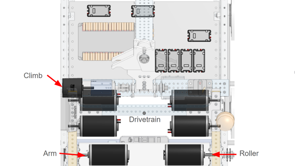
Now we will move to connect the motor controllers to the motors. Before everything is connected, here is an outline of which motors do what.
Below is the motor controller to motor diagram. The motors are plugged into their motor controllers by stripping the ends of the red and black motor wires (if necessary) as well as just the red and black wires coming out of the motor output side of the Spark Maxes. Connect the red to red and black to black using WAGOs or another quick disconnect.
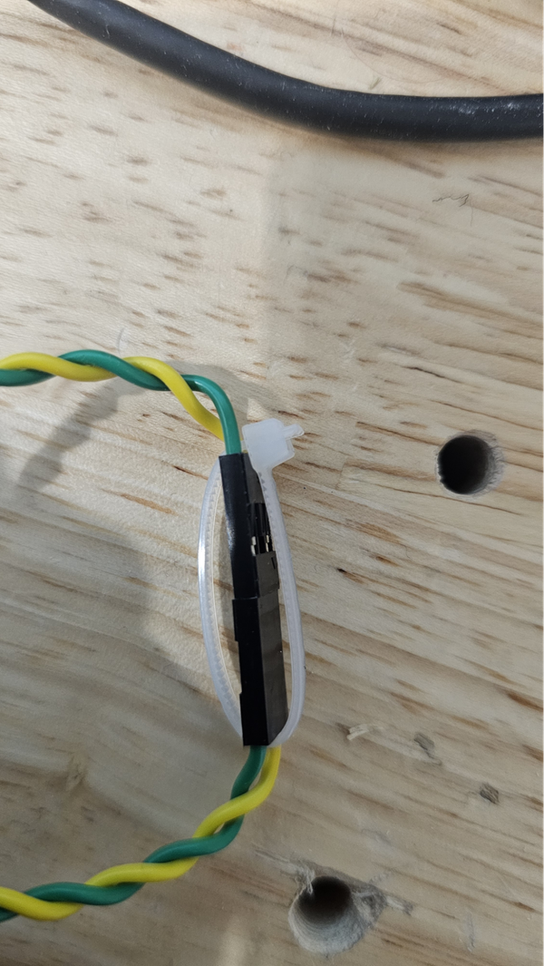
Do not worry about the white wire when connecting CIM motors to Spark Max motor controllers. Wrap some electrical tape around the white wire if it is unused to prevent the wire inside from contacting metal components of the robot. It does need to be connected (along with the hall effect sensor cable) to use the NEO in the Rookie Kit of Parts to power the climbing mechanism.
Here is a rough outline of how our battery is connected to our battery, with the red wire going through the main breaker. Thick 6 gauge wire (provided in the Kit of Parts) is used to connect the battery connector to the main breaker and Power Distribution Hub or Panel. Take one of the provided battery cables with a large plastic Anderson connector on one end and crimp a ring terminal to just the red wire if using a newer REV Power Distribution Hub (PDH) or both the red and black wires if using the older Power Distribution Panel (PDP). Eight 6AWG ring terminals are included in the Rookie Kit of Parts that can be used for this. Make sure the crimp is secure by pulling on it after crimping, if these connections are loose they can and will cause your robot to lose power as they are knocked around in matches.
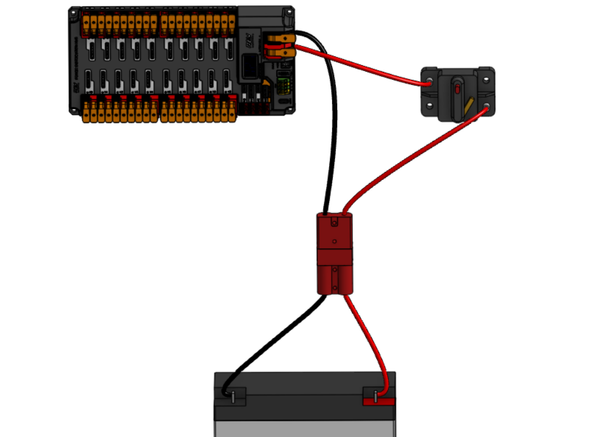
Cut a section of the red 6 gauge wire provided in the kit down to an appropriate length and crimp a ring terminal on one end if using the PDH or both ends if using the PDP. Bolt the ring terminal to the AUX side of the main breaker and attach the other side to the positive terminal of the PDH/PDP. Cover any exposed metal on the main breaker connectors with electrical tape.
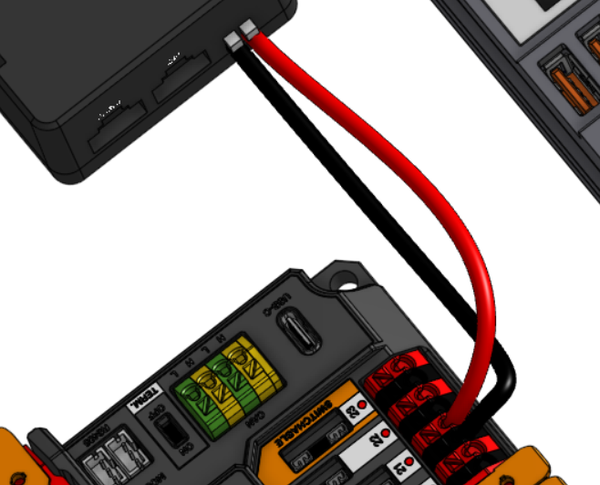
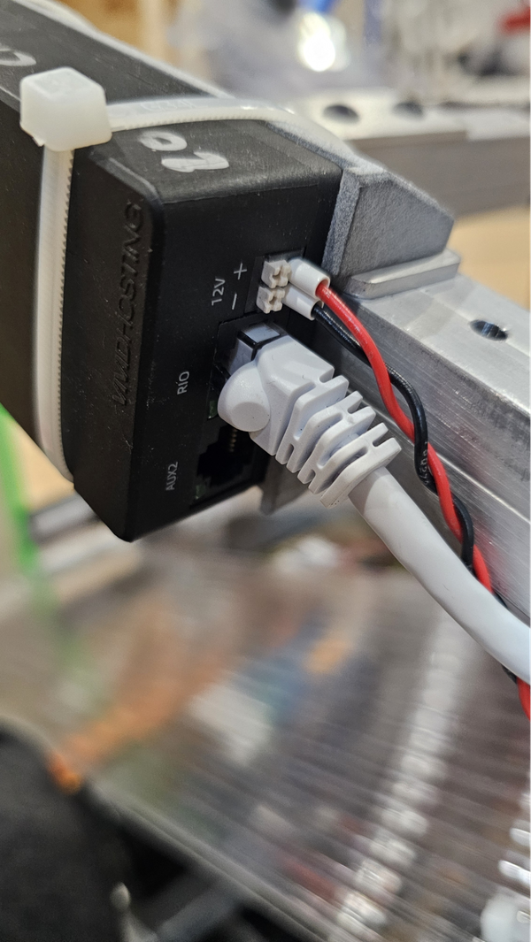
Two pairs of 18 gauge wire run from the PDH auxiliary power slots to the roboRIO power connector and the VH-109 FRC Radio. On the PDH the slots numbered 20 to 22 near the battery voltage indicator can be used for the roboRIO or radio power, just install 10 amp fuses in the slots used. The positive red wire screws into the “V” (for voltage) connector of the roboRIO’s power terminal and the negative black wire goes to the “C” (for common) connector.
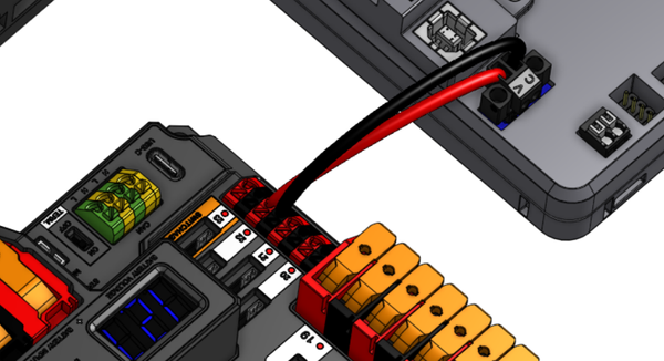
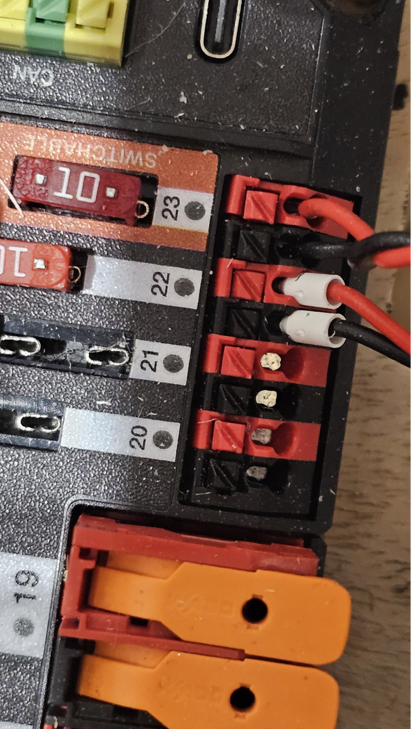
For the radio you will also need to connect an ethernet cable from the port on your roborio to the RIO slot on the radio. Please note that our images show ferrule connectors for the wiring but bare wire works just fine.
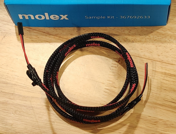
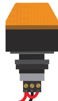
The Robot Signal Light (RSL) visually indicates what state of operation your robot is currently in. It is wired into the RSL port on the roboRIO. The Rookie Kit of Parts includes a 2-wire jumper cable that can have one end cut off and the blue Molex sample kit in the regular black Kit of Parts tote includes a 2-wire cable that has a connector on only one end.
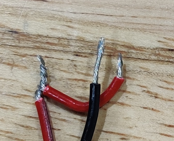
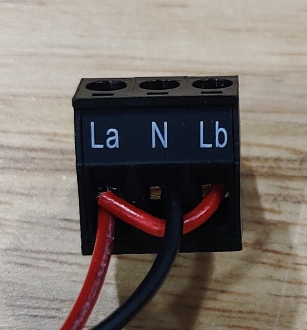
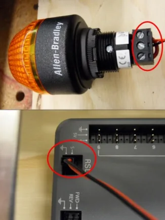
The connector end of either cable is plugged into the RSL port with the red wire in the S position and the black wire in the ground position (the small lines in a triangular symbol). On the chopped off end of the cable, cut off a short section of red wire that will be used to connect the two outer La and Lb terminals. Strip off the ends of the wires and twist one end of the jumper cable with the red wire it was cut off from so that the two wires can be inserted into the same terminal on the RSL. The red wire can then be connected to either outer terminal with the jumper connecting it over to the other outer terminal as well. The black wire is connected to the center N terminal. The screws on the side of the terminal block will clamp down on the wire when tightened. The RSL can be mounted anywhere that satisfies the wording of rule R709, with our suggestion being the on the superstructure.
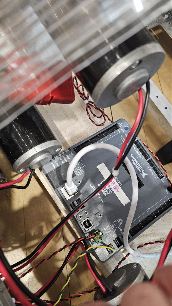
The RSL will then be wired into the Roborio with the red wire towards the center of the board.
Below is a video that showcases how the battery is secured: