Algae Arm
The Algae Arm utilizes the KitBot intake plates to house a motor to allow the arm to go up/down and a motor that powers the intake roller. The Arm will be mounted to the superstructure. The superstructure houses a hardstop for the bottom position of the arm in the form of a rope. There is also a 3D printed hardstop on the superstructure to prevent the arm from going too far into the Coral Basket or Superstructure.
Required Tools
- ⅜” Wrench/Socket
- 5/32” Allen Key
- #7 Drill bit
- 1-⅛” minimum diameter drill bit or step drill bit
- Band Saw/Chop Saw or other metal cutting device
- Drill press (preferred) or hand drill
- 3D printed drill guide if box tube is not patterned (preferred if not patterned)
Algae Arm Materials
Here is a rough approximation of what you will need, bolt counts may be off, items may change based on what you have:
- Qty(6) x 1.5” 10-32 Socket Head Bolts
- Qty(6) x 1” 10-32 Socket Head Bolts
- Qty(4) x 0.5” 10-32 Button Head Bolts
- Qty(6) x #10 or ¼” Washers (optional)
- Qty(12) x 10-32 Nylock Nuts
- Qty(2) x KitBot Roller Plates KB-25001/25002
- Qty(10) x ½” hex shaft collars
- Qty(7) x 2” long ½” hex spacer
- Qty(1) x 1” long ½” hex spacer
- Qty(2) x ½” long ½” hex spacer
- Qty(6) x ¼” long ½” hex spacer
- Qty(4) x ⅛” long ½” hex spacer
- Qty(2) x 1/16” long ½” hex spacer
- Qty(4) x Hex Hubs
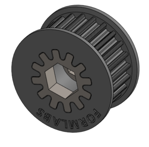
- Qty(1) x 24 tooth ½” hex pulley for 15mm belts KitBot comes with 3D printed pulley and inserts for hex conversion
- Qty(1) x 48 tooth ½” hex pulley for 15mm belts KitBot comes with 3D printed pulley and inserts for hex conversion
- Qty(1) x 130T HTD Belt 15mm wide
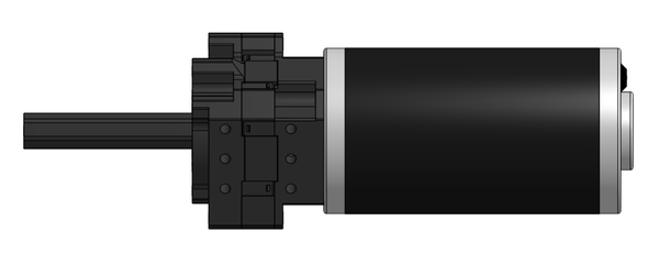
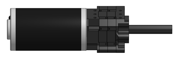
- Qty(1) x 25:1 Gearbox
- Qty(1) x 4:1 Gearbox
- Qty(2) x CIM
- Qty(2) x Clamping Bearing Blocks
- Qty(5) x 4” Thrifty Squish Wheels
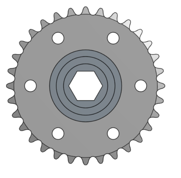
- Qty(2) x 18T ½” hex bore #25 sprocket
- Qty(2) x 32T #25 plate sprocket
- Qty(6) x ½” long 0.196” ID spacers
- Qty(4) x ½” hex bearing (can be for rounded hex)
- Qty(1) x ⅛” Paracord - 50ft
- Qty(4) x ¼-20 0.75” thread forming screws (should be left over from the chassis)
You will need to make:
- Qty(1) x 26” long ½” hex shaft
- Qty(1) x 25” long ½” hex shaft
- Qty(2) x 18” Churro (can also be hex shaft, should be left over from the chassis)
- Qty(2) x 20” long 2x1 04_Algae_Arm_Tubes
- Qty(1) x 03_Back_Stop
- Qty(1) x 04_Corrugated_Plastic_Guard
Algae Arm Machining
Start by cutting all the required stock to length, you will have one 26” ½” hex shaft, one 25” ½” hex shaft, two 18” churros (can be hex shafts) and two 20” 2x1 tubes.
Algae Arms
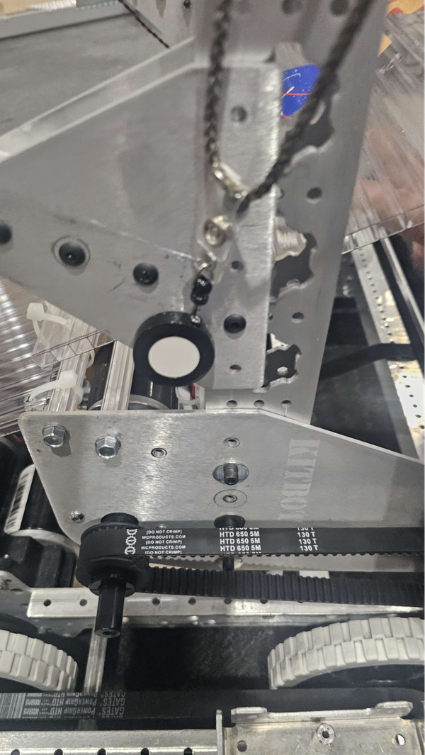
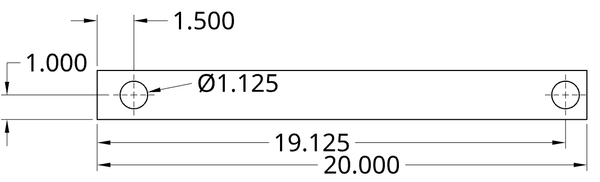
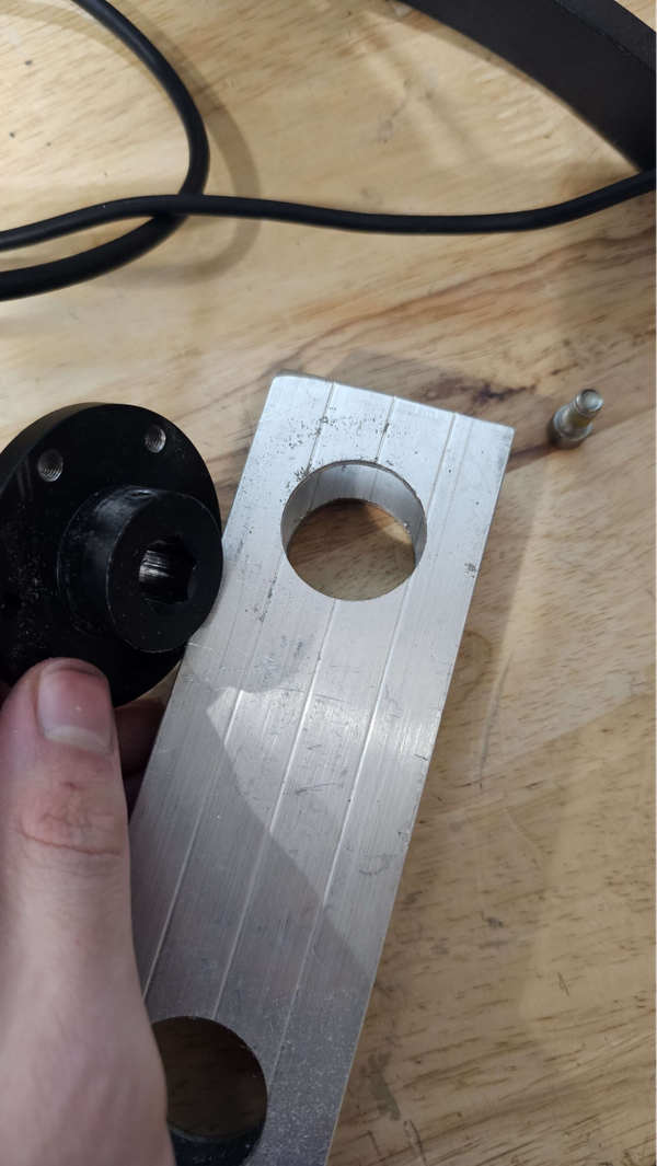
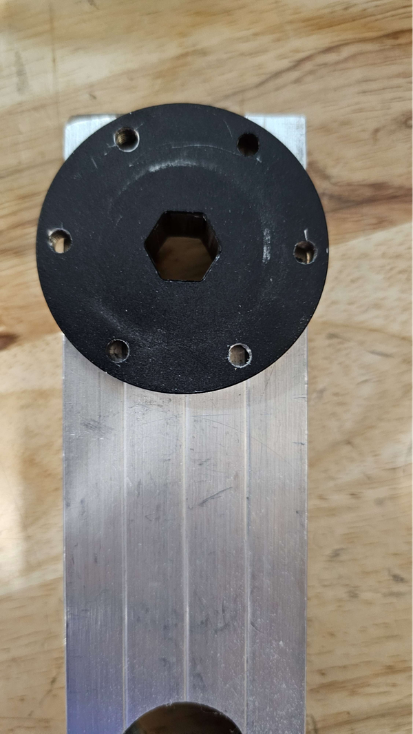
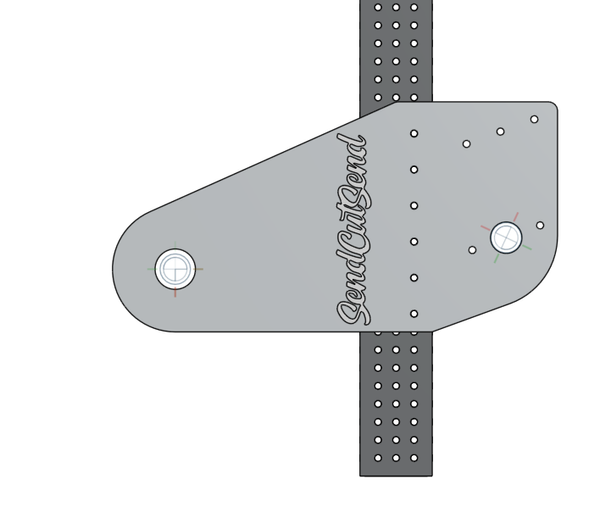
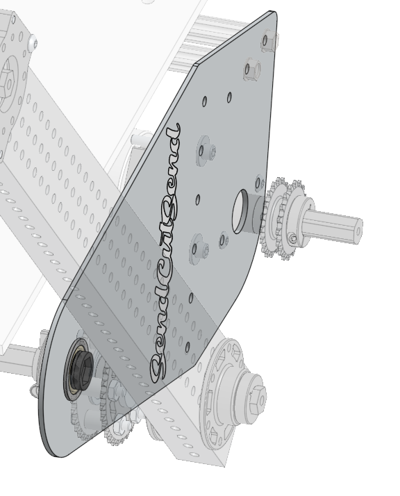
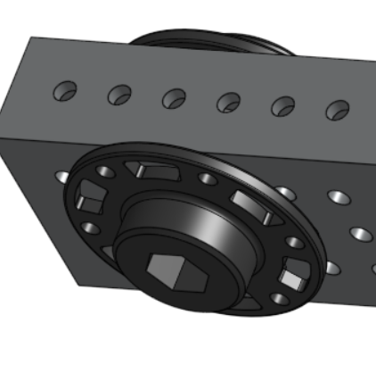
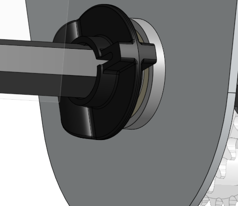
The Algae arms require two 1.125” (1-⅛”) holes. One of the holes is where the hub will be attached and we will use the holes to match drill out the locations that we want, the other will be for the hex shaft. Using the drill guide you will want to make a pilot hole before using your step drill bit. For the 19.125” holes, it can be slightly off as we will use a bearing block to ensure we have a tensioned chain.
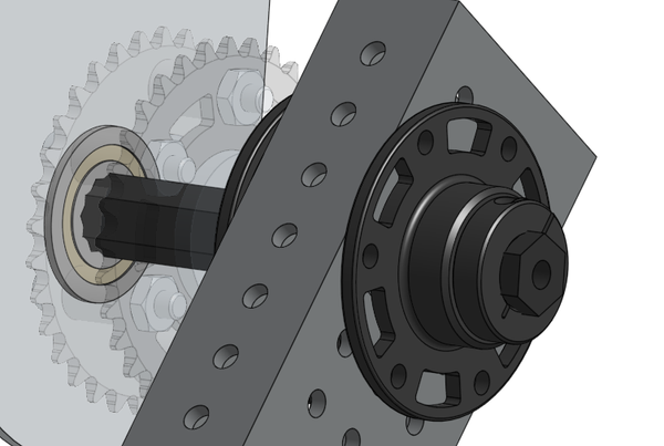
You will need to attach hubs on both sides of the 1.5” holes, to do this press your hub into the 1.125” holes and use the hub as a guide for your holes. It is best practice to put a bolt through the hub after one hole has been drilled to ensure it will not shift. The size of holes may change based on your hub but #7 holes should work in most cases.
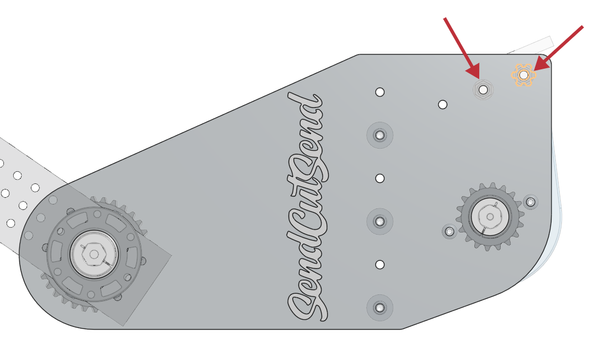
KitBot Roller Plates
We highly recommend that you purchase these. If you are using churros here, you can drill out the two marked holes to ¼” but the self tapping screws should work with the included holes.
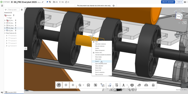
Various Spacers
Many of the spacers needed can be bought but if you want to save some money they can be manufactured. These spacers can be 3D printed or cut from ¾ in. Schedule 40 PVC Pipe. The spacers can be directly printed directly from exporting the file in the CAD by right clicking and selecting export.
- Qty(7) x 2” long ½” hex spacer
- Qty(1) x 1” long ½” hex spacer
- Qty(2) x ½” long ½” hex spacer
- Qty(6) x ¼” long ½” hex spacer
- Qty(4) x ⅛” long ½” hex spacer
- Qty(2) x 1/16” long ½” hex spacer
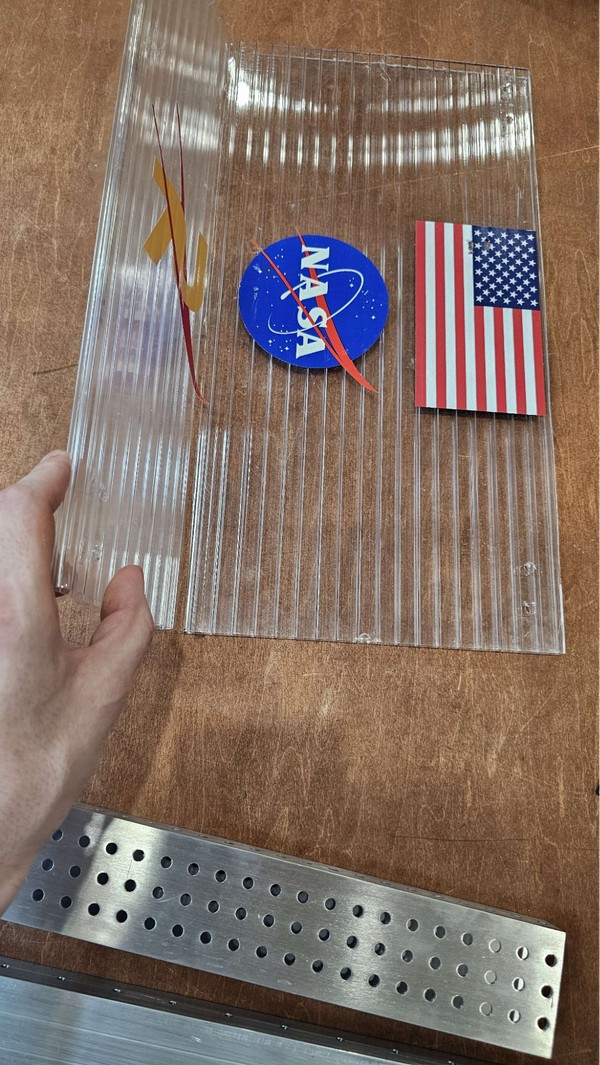
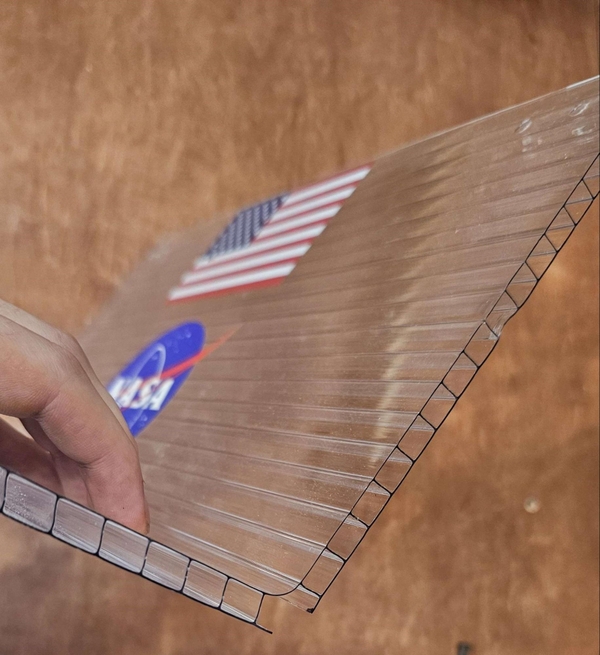
04_Corrugated-Plastic-Guard
The corrugated plastic guard will be ~12” by ~12”, the holes can be drilled later on to #7 size when you have an understanding of where you want your zip ties. When cutting the plastic, pay special attention to the direction of the ribs. You want the rips running from left to right, so it is easier to bend later.


Algae Arm Assembly
Start by assembling your 4:1 and 25:1 Gearboxes. We used two REV Max Planetaries but CIM Sports could be used instead (20:1 would be an acceptable alternative). We used a CIM motor in both of these.
If you are using a CIM Sport you will need a Sport Gearbox Face Mount Spacer for each CIM Sport.
Additionally the output shaft will be a bit shorter than desired, to fix this you can cut a length of shaft that will fit all the needed hardware and retain the stack with a bolt and washer.
The 4:1 is used for the intake motor and the 25:1 is used to control the position of the Algae Arm.
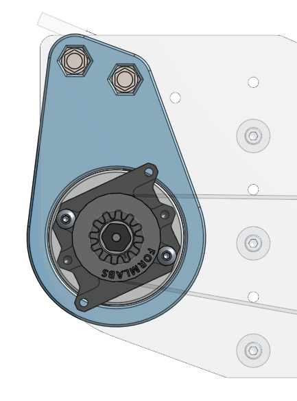
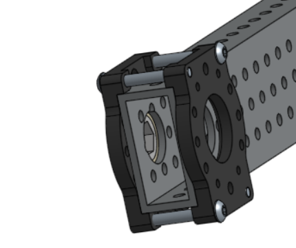
Next comes the attachment of the KitBot Roller plates to the superstructure. The lowest hole will be 8 holes up or 4” up from the base of the 03_Superstructure_Uprights. It will be mounted to the hole grid column closest to the center of the robot. Use three 10-32 1.5” Socket Head bolts with Nylock nuts and optionally use some washers.
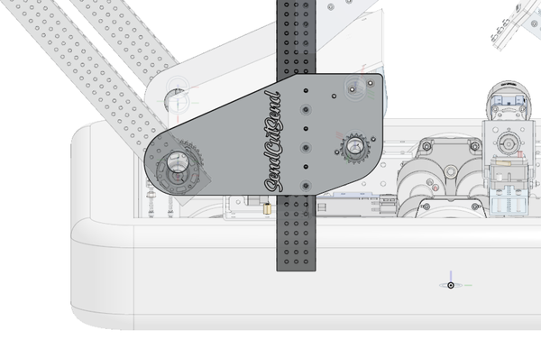
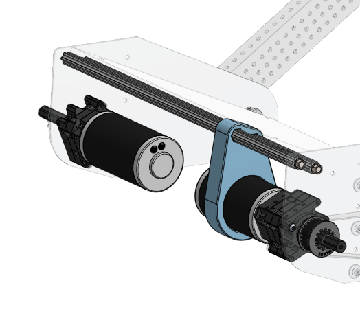
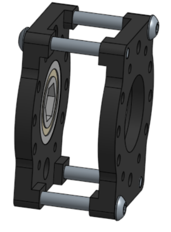
Next take your two 18” churros (or hex shaft) and your 03_3DP_Algae_Motor-Support. Slide the two churros into the upper two holes, making sure that the large hole will be inside the plates instead of above it. Once the 3D printed part is in place, the two churros can be attached to both sides using the self tapping screws from the chassis.
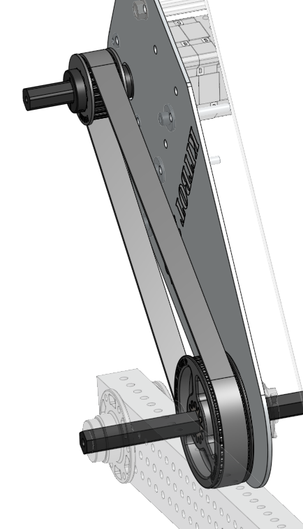
Next, attach the gearboxes to plates with two 10-32 0.5” Socket Head Bolts. We attached our 25:1 gearbox on the same side as the gearbox winch but there is no reason you cannot reverse the sides except for inverting how the default code works. Remember that belts will be used with the 25:1 gearbox and chains will be used with the 4:1 gearbox. The 03_3DP_Algae_Motor-Support will need to slide over the CIM on the 25:1 gearbox to help improve the rigidity of the system.
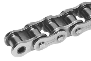
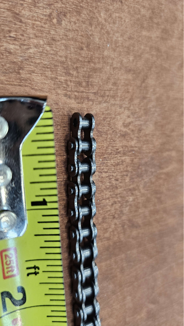
Buckle in, we need chain.There are two lengths of chain, one of 100 links and the other with 166 links. What you might normally think about as a link of chain actually comes in two variants - an “inside” link and an “outside” link. If you look closely at the roller chain, you will see that the “sides” of each alternating link are either inside or outside of the two next to it.
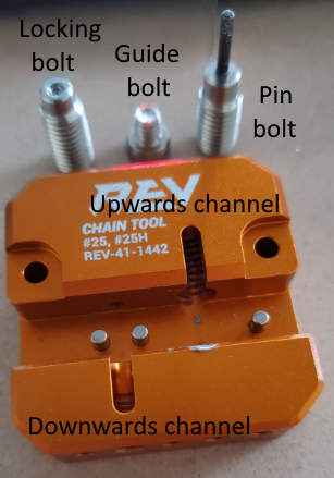
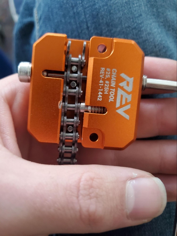
Looking at the #25 roller chain, find the first section of chain that has pins through both holes of an outer section (in the photo above, this would be the second link in from the left). Set up the chain in the #25 chain tool so that the pin closer to the free end of the chain in this outer section is lined up with the channel cut towards the bottom of the tool (usually towards the left of the tool). The shorter bolt that extends into the channel cut upwards into the tool (usually to the right) is tightened down to the chain to hold it in place (and used in reassembling the chain later) and the longer bolt with a pin attached is tightened down onto the chain to push the pin in the chain links out. Some chain tools also have a third shorter bolt that can be inserted into the bottom of the downwards channel to prevent a pin from being fully knocked out - insert this if your chain tool has it. Begin tightening the pin bolt down so it starts to push the pin in the links of chain out of the upper outer plate and into the lower channel. If your tool does not have the additional bolt in the lower channel to prevent a pin from being fully pushed out, back out the pin bolt often to check when the short, unwanted section of chain is finally free before the pin is fully pushed out of the bottom outer plate of the link we want. If the pin does pop out of the outermost plate, try again on the next full outer plate. This pin will be pushed back into place around the chain tensioner shortly.
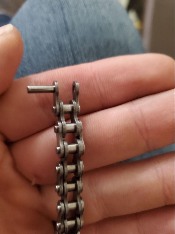
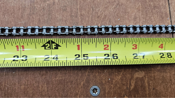
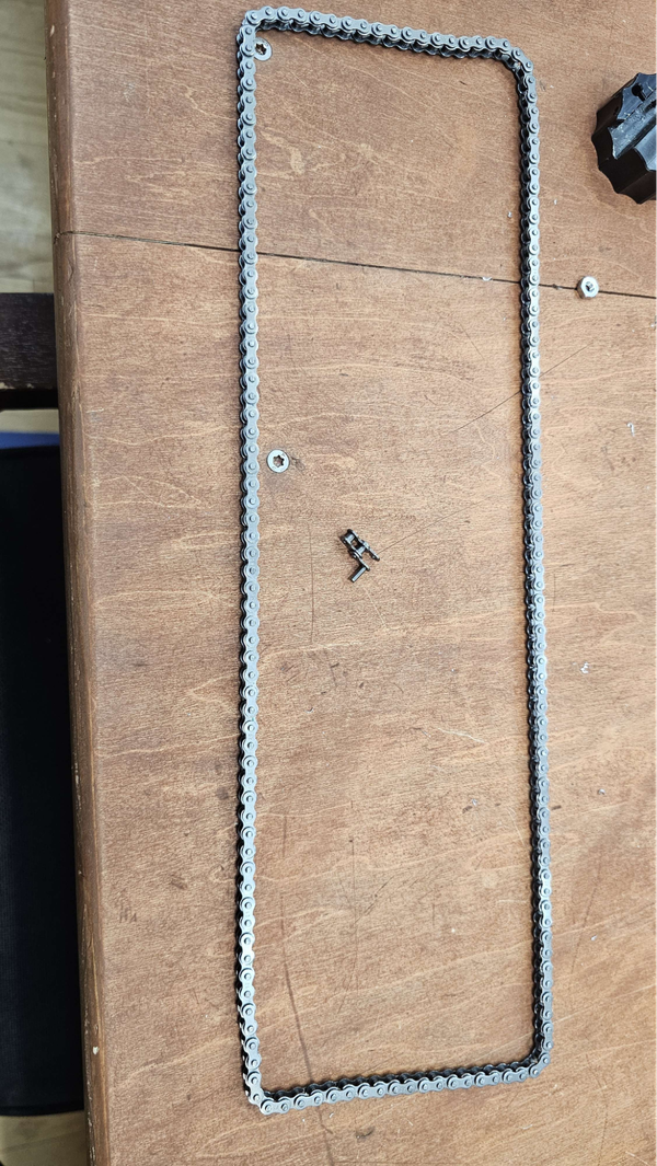
After getting an exposed outside link you will need to get an inside you as well, once again you need 100 and 166 links. #25 chain has a link every ¼” inch, so a 100 link chain will be 25” and the 166 link chain will be 41.5”.
Remove the bolt previously used to hold the chain in place from the tool and reposition the chain inside the tool with the pin now sitting in the upwards channel. Place the inside link inside the outer plates of the chain so that the pin will trap it in place when it is pushed back in. Retighten the locking bolt down so the “cup” at the end of the bolt starts to push the pin back through the outer plate of the chain, and then switch to the longer pin bolt to fully reinsert the pin through both outer plates. Congrats you have finished your chains!
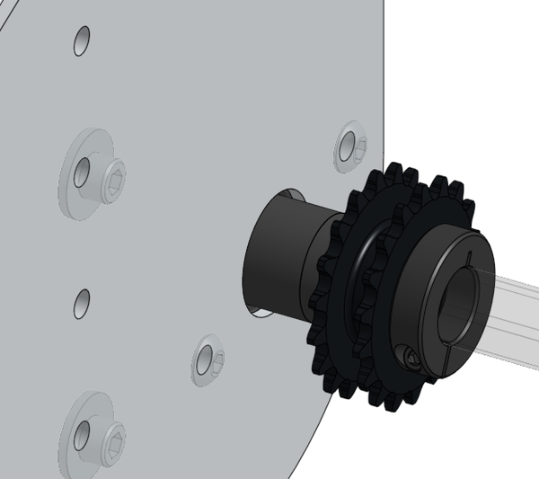
Next we will prep the self-assembled 32 tooth double sprocket. Start by pressing bearings into both of your 32 tooth sprockets. First grab your 26” hex shaft, a ½” hex bearing, 1/8” long ½” hex spacer and a 1/16” long ½” hex spacer, slide the spacers onto the shaft. The bearing can be pressed into the outer plate on your sprocket side.
A ¼” long ½” hex spacer and a ⅛” long ½” hex spacer. Slide the shaft through the spacers, making sure that the flanges of the bearings face the inside of the assembly.

Next you will need six 0.5” long .196” id spacers, 1” 10-32 Socket Head Bolts and Nylock nuts.
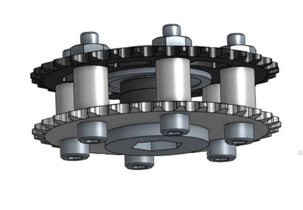
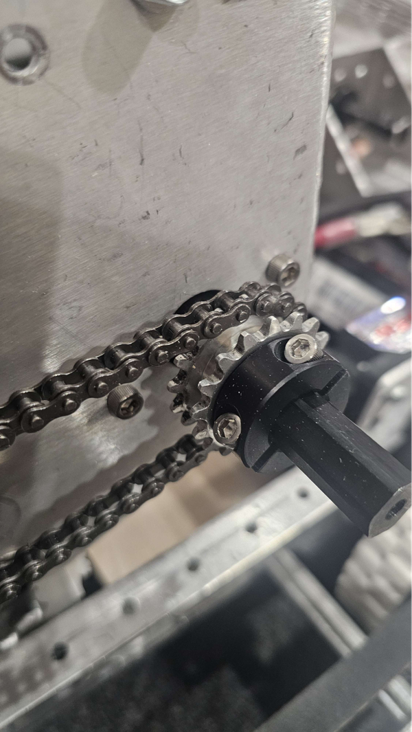
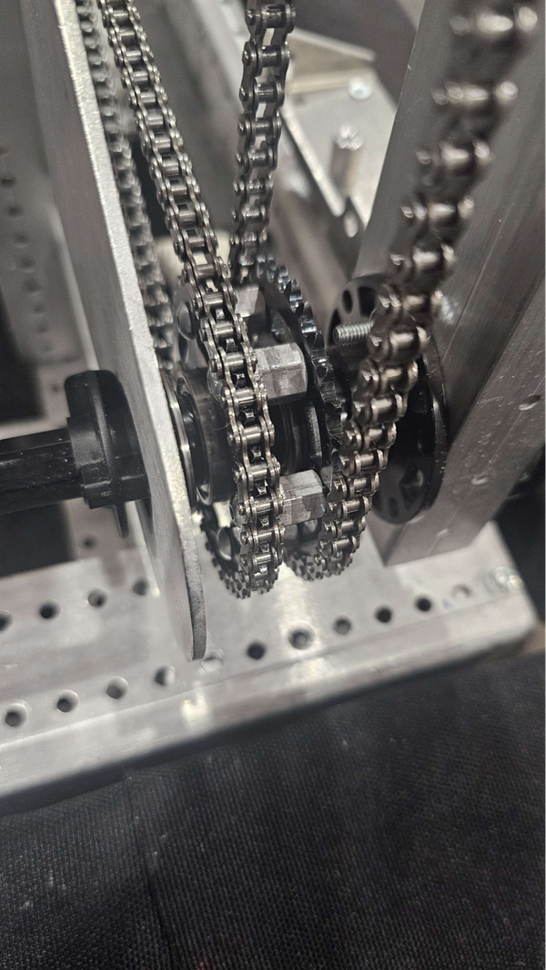
Next grab ½” long ½” hex spacer, a ¼” long ½” spacer, a 18 tooth #25 chain sprocket and a clamping shaft collar. Take the chain and run it on the inside sprocket of the 32 tooth sprocket assembly and the 18 tooth sprocket. Put the spacers on the shaft of the 4:1 gearbox then add the sprockets, keeping the chain on both of them. You may need to mess with the spacers to ensure the sprockets line up. When finished add a clamping shaft collar to the end of the sprocket on the gearbox shaft.
If you have the 24 tooth pulley that came with the KitBot you will need to press the two included inserts into the pulley. This can be pressed by hand, with a clamp, vise or press. Be careful to not use too much force with the heavier duty options. Do the same to the 48 tooth pulley, if instead you have the ThriftyBot 48 tooth pulley, you will need to attach a hex hub to it.
We will look to add the hardware on the pulley side, starting by adding an ⅛” long .5” hex spacer, a ¼” long 0.5” hex spacer, your 24 tooth pulley and a shaft collar in that order to the end of output of your gearbox. Tighten down the shaft collar so the pulley cannot walk.
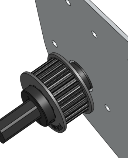
Next we will add the hardware to the 26” hex shaft, we will add a ½” hex bearing, ⅛” long hex spacer and a 1/16” long hex spacer in that order.
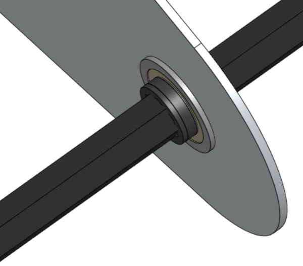
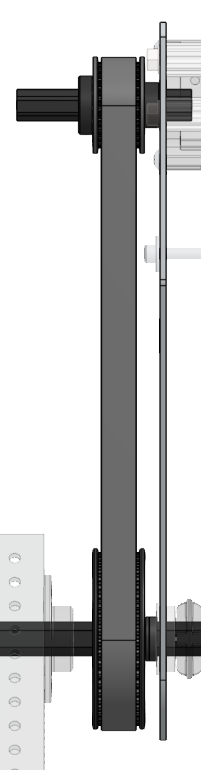
Afterwards, grab the 130 tooth belt and wrap it around the 24 tooth pulley. Then slide the 48 tooth pulley onto the hex shaft. Spin the pulley while trying to get the belt on, you should be able to get over the flange onto the pulley.
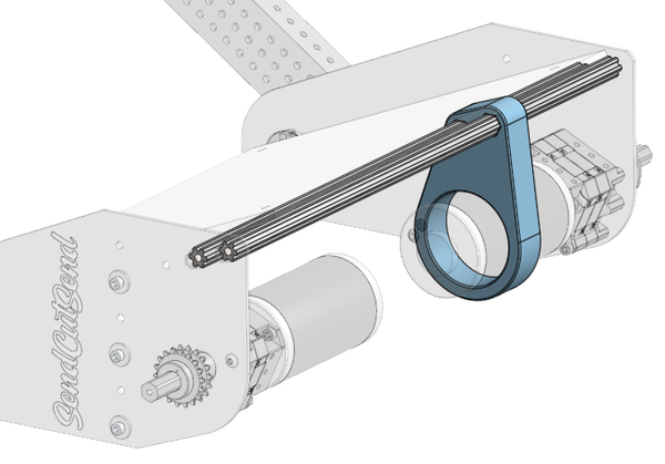
Next attach a hub to each side of your two 04_Algae_Arm_Tubes via bolts and nuts, the hardware will differ based on what hub you have. But generally 10-32 1.75” bolts and Nylock nuts will work fine.
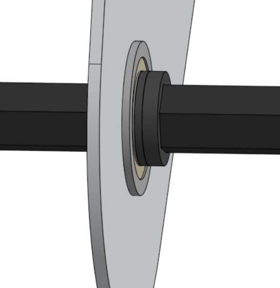
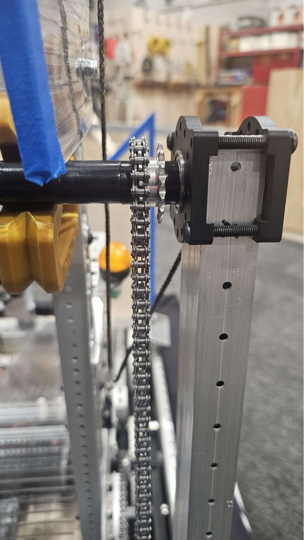
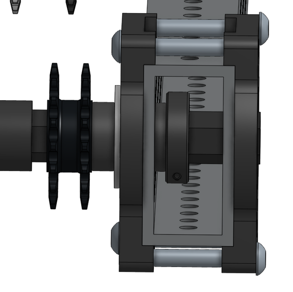
We will be adding the two thrifty bearing blocks. Start by grabbing one ½” hex bearing and a bearing block. Insert the bearings with the flanges facing the inside of the block. The bearing blocks will go on the end of the 04_Algae_Arms with the bearing on the side that is towards the center of the robot. Make sure that the bolts go through the non-threaded side into the threaded side and are tightened in a star pattern.
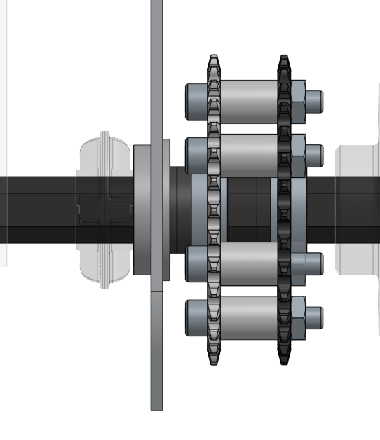
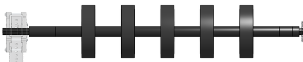
Next place the chain onto the open side of the 32 tooth sprocket and insert a hex shaft into the bearing block on the opposite side of the chain. You will then need to add the following hardware in order: (assume all spacers are ½” hex spacers)
- Two 2” spacers
- 4 Inch Thrifty Squish Wheel (TTB-0057)
- 2” spacer
- 4 Inch Thrifty Squish Wheel (TTB-0057)
- 2” spacer
- 4 Inch Thrifty Squish Wheel (TTB-0057)
- 2” spacer
- 4 Inch Thrifty Squish Wheel (TTB-0057)
- 2” Spacer
- 4 Inch Thrifty Squish Wheel (TTB-0057)
- 2” Spacer
- 1” Spacer
- ½” Spacer
During this process it will be easiest if only the pulley side of the 04_Algae_Arm_Tube is attached.
From here, put the chain onto the 18 tooth sprocket while ensuring it stays on the 32 tooth sprocket and push them onto the hex shaft. You may to play with the length of your hex spacers to make sure everything lines up depending on your sprockets.
Now add a ¼” hex spacer onto the roller hex shaft and then add the other 04_Algae_Arm onto the end. You will then need to add ¼” hex spacers on the inside on the tube, then a clamping shaft collar. This will be done on both sides.

Finally add shaft collars on the outside of both 04_Algae_Arm_Tubes and on the inside of the KitBot plates.
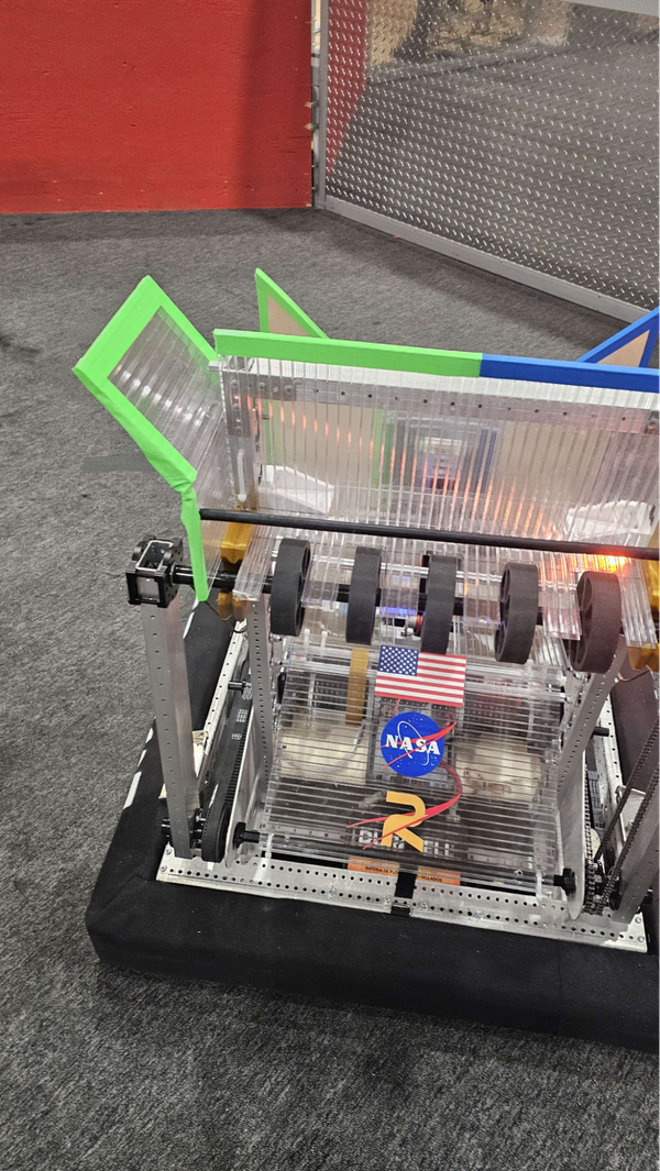
Add the corrugated plastic, which will be attached to the rear churros and LOOSELY to the hex shaft via zip ties. You will need to make holes in plastic to attach it, these holes can be ¼”. To make accessing the battery easier we also recommend that you cut a slit with a utility knife into the corrugated plastic. By only slicing a single layer it will be able to bend nicely, our line was about 4.25” from the bottom on the battery side. We also recommend taping the corners to prevent cuts from the sharp plastic.

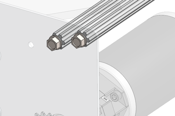
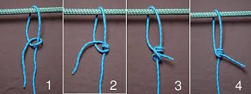
The final step is to add the bottom hardstop for the Algae Arm. This will be done with paracord. Start by tying some paracord around one of the eye bolts. You will want to tie a taut line hitch knot to both your eyebolt and a bolt on bearing block. This knot is beneficial as it will tighten when pulled, so we will secure the rope a bit higher than desired and running the intake up and down a few times will pull it into the desired place. Here is a diagram of how that knot is tied.
Once that knot has been tied to the eye-bolt, put the Algae underneath the intake wheels, with the Algae against the bumpers. Tie the other taut line hitch around the innermost bolt of the bearing block. Do this on both sides.
When done, cut the paracord to prevent fringe and use a lighter to singe the end to prevent fray. The final step is to use badge clips to keep the cables from getting caught in anything. We found the badge clip was easy to clip onto the bottom of the 70 degree gusset.