Reading Part Drawings
The Everybot manual will use engineering "drawings" like the one below to aid you in machining parts of the bot correctly. This part is from the 2022 Everybot but we will use it as an example.
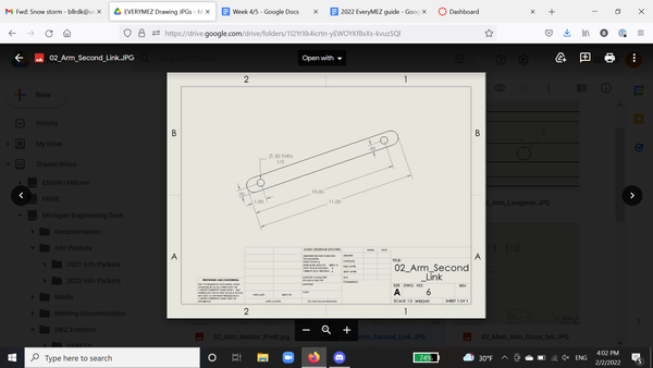
The name of the piece you are looking at is in the bottom right corner. For the purposes of this manual, all dimensions on all drawings are in inches.
Each line with arrows and a number through it or next to it are a type of dimension. The arrows point towards lines which extend to the points on the part that the measurement is taken between - that is to say, if you took a tape measure and lined the beginning of it up with where one of the lines points on your physical part, and then extended it to where the other line points, the tape measure should read the number located between the two arrows on the drawing.
The bottom most marking of 11.00 in the blue box gives the dimension for the entire piece. For this part in particular both ends were rounded, making this a particularly confusing part to "read." Most drawings will reference all measurements from a single edge of the part.
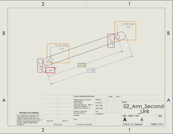
The drawing shows that the arm link will have two holes. Dimensions referencing the location of holes are measured to the center of the hole - this allows you to scribe (see the Measurement and Marking section if you do not know what this means!) the center of the hole and center punch (ditto!) it to mark where to drill. One hole is centered 1.00 inch from the reference edge (the red box), and the other will be 10.00 inches from the reference edge (green box). These two dimensions also tell you several other things not in the drawing - for example, the centers of the two holes are also 9.00 inches apart from each other.
Both of the pink boxes tell you that the center of each hole is .50 inches away from the edge of the bar. Because this link is cut from 1 inch by 1 inch tube stock, you know that these holes are centered across one of the 1 inch faces - if you mark 0.5 inches from one side of the bar, and then measure from your mark to the other side, it should also be 0.5 inches from that side. Not all holes are centered in this way.
The last dimension on this sheet is the diameter of the hole in the orange box. This is also the size of the drill bit you will want to drill that hole with. “THRU” means that it goes all the way through the box tube. Holes without “THRU” only go through a single side of the box tube.
Technical drawings are complicated and can be hard to understand initially. We suggest trying to go through each drawing slowly and mark the parts you understand down onto your physical pieces as you go. Don’t forget to double check your work before you cut and drill!