Measurement and Marking
Measurement Tools
- Tape Measure: Used for measurements longer than calipers or low precision measurement.
- Digital Calipers: Use for higher precision measurements at shorter distances (typically <= 6").
- Speed Square: Use to ensure straight lines and squareness between parts.
Marking Tools
- Digital Calipers: In addition to being good for measurement they can make scribe groves in aluminum.
- Marker (sharpie): Use in combination with tape measure and speed square for straight lines.
- Center Punch: Used to mark the center of holes for drilling, typically used in combination with calipers.
Marking For A Cut With A Tape Measure
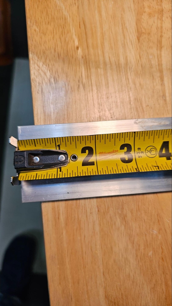
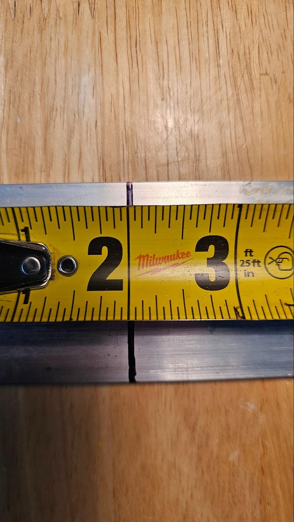
Reading The Tape Measure
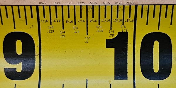
A typical tape measure is around 25 feet long and will have markings every 1/16" of an inch that divide the inch down for more precise measurement. The longest of these markings is at the half inch (1/2”) point between two inch markings. The next highest lines mark the 1/4” and 3/4” positions, with the 1/2” mark already where the 2/4” position is. Four slightly shorter lines mark the other 1/8” increments along the inch and the shortest lines mark the remaining 16ths of an inch.
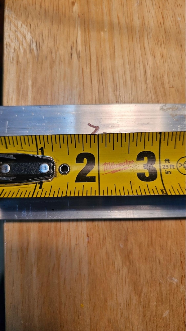
A Tape Measure's Precision
Let's say that you need to mark a line at 7.90". Where should the mark on your workpiece be? Well, 7/8" is equal to 0.875 of an inch while 15/16” is 0.9375, and both 7/8 and 15/16 are marked on a tape measure, so it would make sense to mark somewhere between these two lines. With a tape measure and a marker it doesn't necessarily matter too much, either line will work fine, especially if a thick marker like a Sharpie is used. Always be as precise as possible but know that if you are using a tape measure there is likely to be some amount of error. For some components this may not end up mattering and most components on the Everybot are designed with an error tolerance in mind.
Making The Line
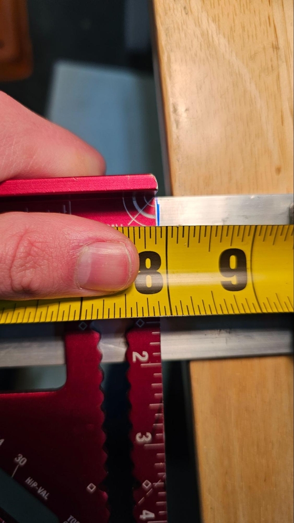
In general, when you are marking lines on a piece of stock it is so they can be cut along those lines. A speed square or combination square can help to precisely mark lines for cutting components. Let's say we need to cut some tube stock to exactly 2.000 inches. If the hook of the tape measurer is on the left, we will aim to keep everything to the left of the 2" mark and cut whatever is to the right off at that point. Start by hooking the tape measure to the left end of the tube stock, stretching the tape measure further out down the tube stock so you can work around the 2” mark. Lock the tape measure in place so it stays extended and place it so the tape lays flat on the top of the tube stock.
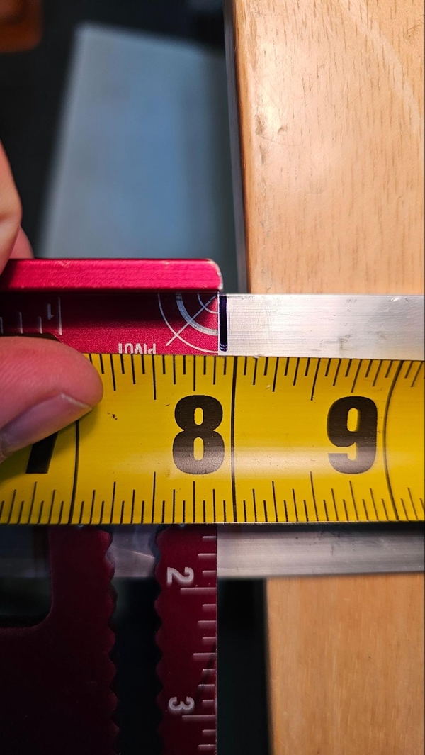
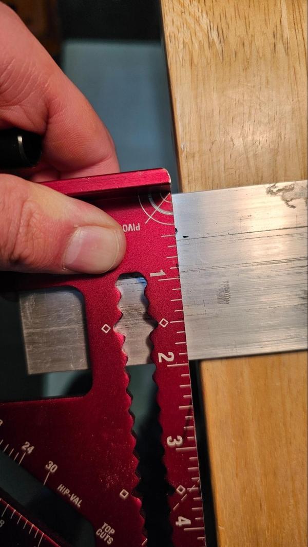
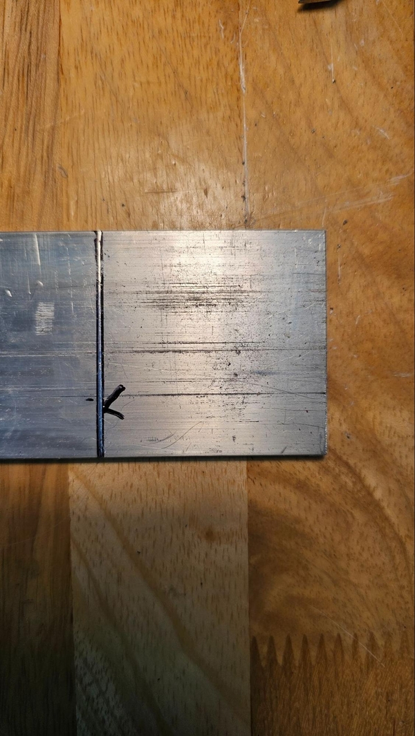
Now take your marker and make a sideways check mark such that the lowest point of the check is as close to the 2" point as possible. The check mark should be on the keep side.
Now grab your speed square, line it up with the tip of your check mark, and make a full line from top to bottom with the marker.
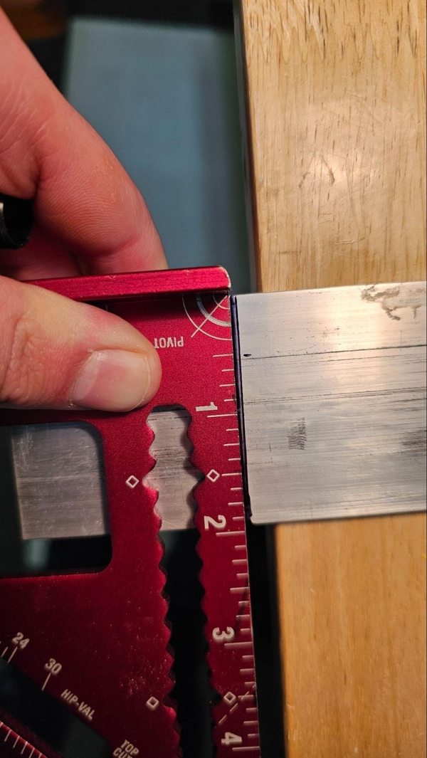
When this part will eventually be cut, you will want to make sure that the cutting tool blade is biased towards the non-keep side of the cut line with the outermost part of the cutting tool’s blade lining up with the inside of the line, right at the edge of the two inches of stock we want to keep . Depending on the cutting tool some extra room may be given.
Can we get more accurate?
Marking For A Cut With Digital Calipers
Some Digital Caliper Basics
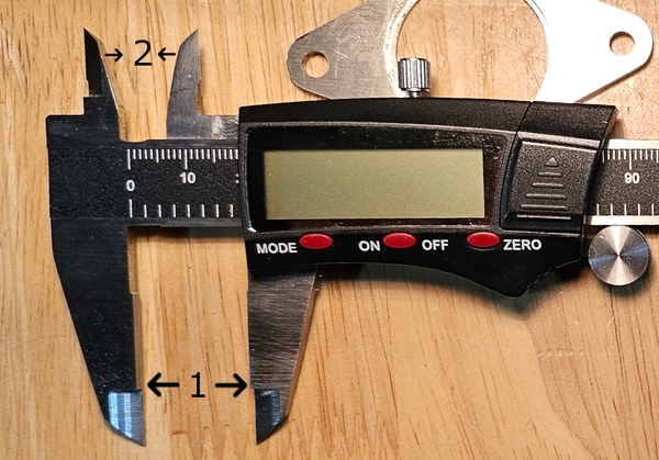
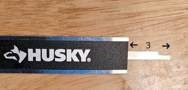
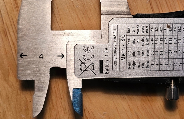
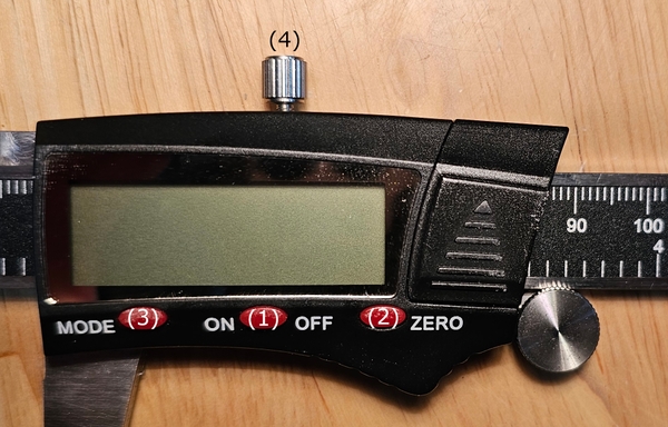
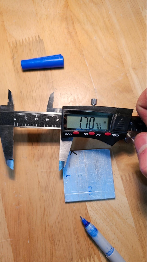
Digital Calipers are a significantly more precise measurement tool than a tape measure. They are able to take measurements in 4 main ways, with the large outside jaws (1), smaller inside jaws (2), depth rod (3) and the step (4). The larger outside jaws are used more often to measure distances or the outside width of a component while the inside jaws can be used to measure the inner diameter of a hole or tube.
Digital Calipers have an electronic display with three buttons, an on/off button (1), a button to set the current position as zero (2) and typically a button to change units (3). They also have a set screw (4) that can be tightened to fix the moveable jaw in place.
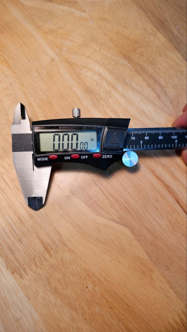
To start using calipers, turn them on, make sure that both sets of jaws are free of debris and lightly press the jaws together. Hit the zero button. Note that the tips of the jaws can be sharp.
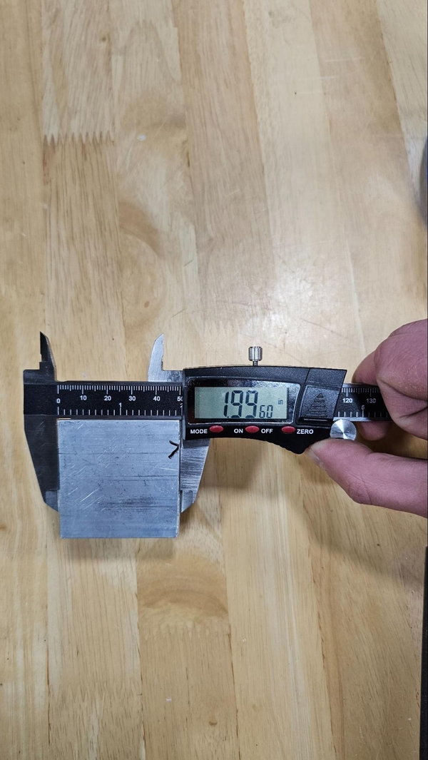
Lock In A Measurement
Let's try to make a 2.000" cut mark again, this time using the calipers. After they have been zeroed try to move the display side until it reads 2.000" +/- 0.0005". Use the screw to lock the calipers in place once you have achieved your measurement.
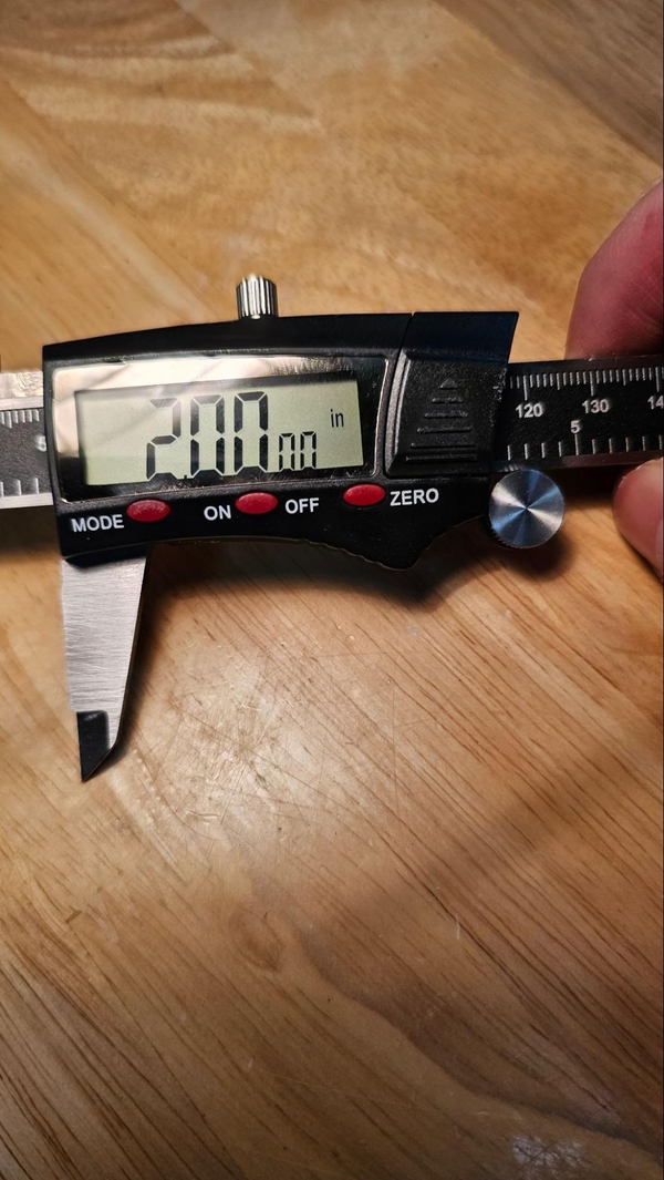
Moving the calipers effectively is a learned skill. Most digital calipers will have a fine adjust wheel and knurled spots for larger adjustments. On cheaper calipers the fine adjustment wheel may be touchy and if so try other methods of adjustment.
Just like many other shop tools, calipers favor right handed individuals. It may be easier for left handed beginners to use the calipers upside-down.
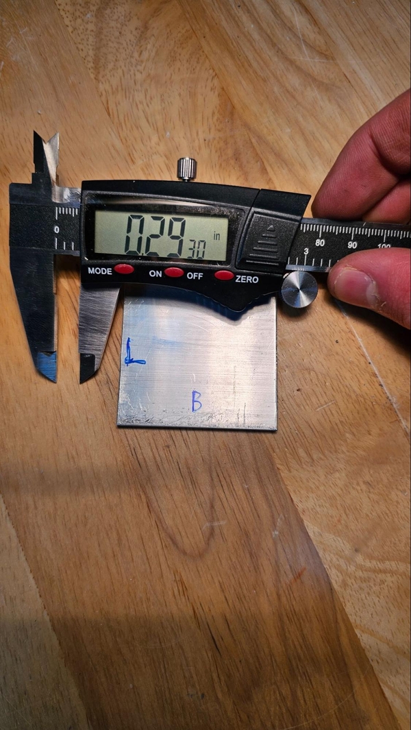
Scribe The Line
With 2.000" +/- .0005" locked in on the calipers you can scribe the desired line. Some people may find it easiest to put their part in a vice but this is not required. To scribe our line we will use the large outside jaws, starting by lining up the jaw attached to display with the edge of your part. This method of marking should only be done with your team’s tools. Over time the point of the caliper will degrade, resulting in less accurate measurements.
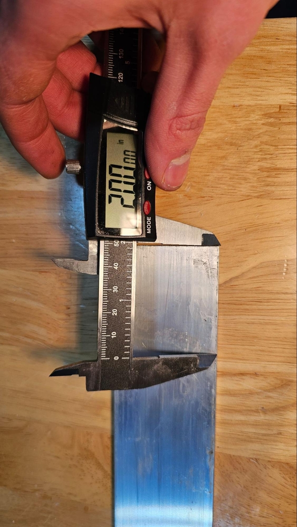
When ready, start towards one end of the part and press the locked jaw into the surface of the part and slide the calipers to the other end, making sure to keep the un-fixed jaw perpendicular to the edge of the part. If the edge of the part is not uniform, file it, making sure it is relatively flat.
There should be a visible grove in the part. If the grove is not very visible a second pass may help, as well as making a thick line with a Sharpie or other marker and then scraping the line through the mark.
When cutting the part you will still need to keep in mind the thickness of the cutting tool’s blade, making sure that you do not cut into the desired “keep” section of the stock.
Marking For A Hole With Calipers
Reading The Drawing
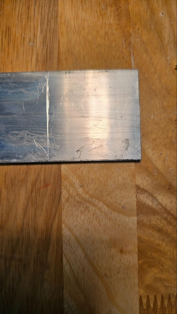
Let's say that you have a 2" piece of 2x1 box tube and you want to make the following:
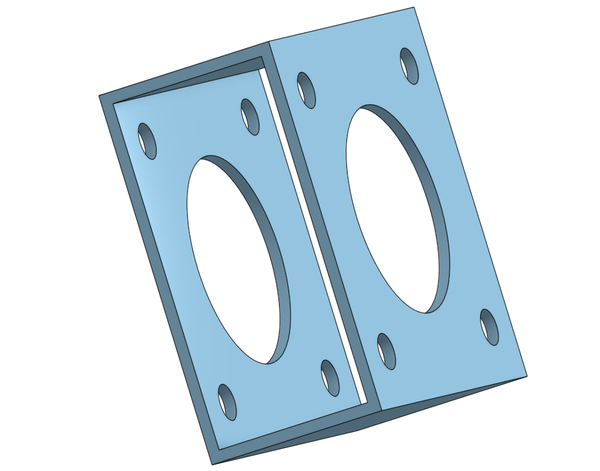
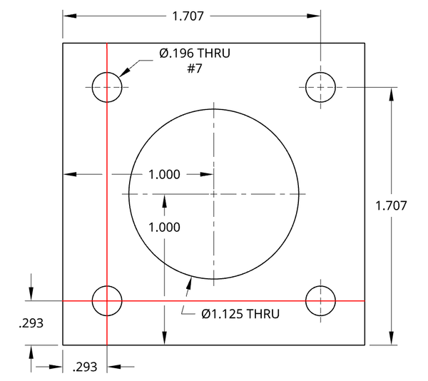
You are then given this drawing:
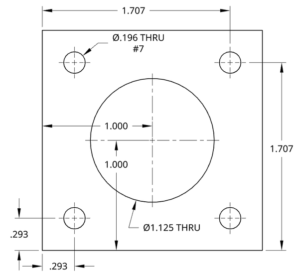
The units on the drawing are in inches. At first glance, some holes seem to be missing dimensions, but this is intentional to keep the drawing less cluttered.
There is only one smaller hole called out as being .196" THRU (through the entire part) but the creator of the drawing expects you to reason that the other similarly sized holes should also be .196". Sometimes it may have been called out like ".196 THRU (4)" but this may not always be the case. The drawing also calls for a #7 drill bit despite this resulting in a slightly oversized hole. Generally, you should follow the drill bit call out if provided.
Additionally the location of each hole is not explicit. Once again you are expected to make some assumptions. For instance, we should assume the upper left hand hole's length will be 0.293" just like the hole below and will also share the height of 1.707" with the upper right hole. If holes have dimensions that do not line up with nearby holes they should be called out to clearly be different from nearby holes.
Notice that all vertical dimensions are taken from the "bottom" of the part, with all the horizontal dimensions taken from the "left" of the part. This helps to keep all the dimensions lined up relative to the same reference points, cutting down on error introduced by measuring from different edges (measuring from opposite ends of a work piece assumed to be the correct length when it is really under or over sized will cause the holes to not line up relative to each other).
Scribing With The Calipers
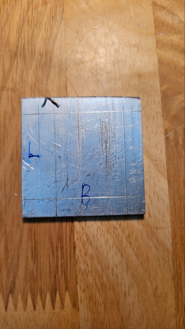
Let's start by setting our calipers to ".2930 +/- .0005". Next we need to find ideal surfaces for our "bottom" and "left". Assuming the bottom and top are the walls of the box tube, this shouldn't really matter as they will always be “factory” edges. When selecting a "left" surface you want to find the smoother, flatter surface, ideally an un-machined factory surface but if this is not possible choose the best-filed side. You may want to mark those edges.
Scribe the following red lines:
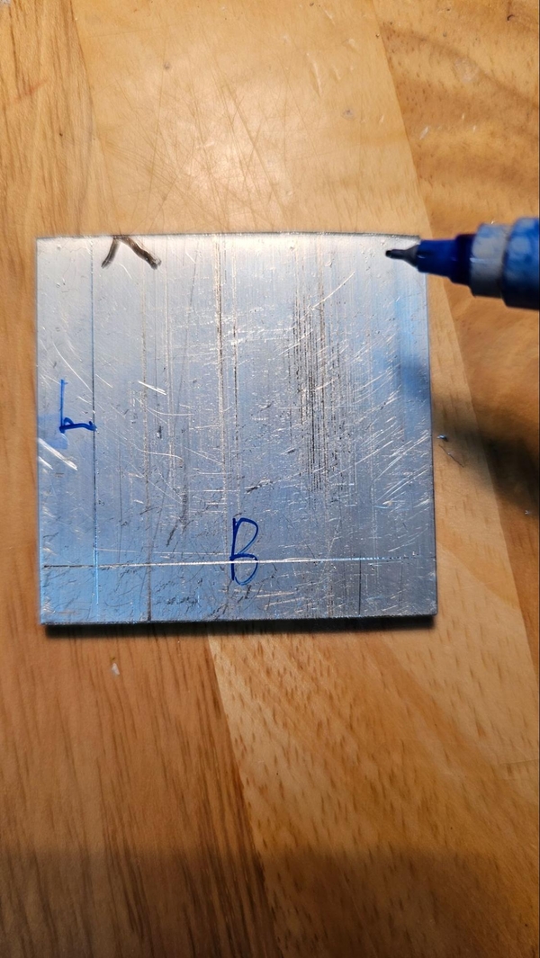
The intersection of these two lines mark the center of the bottom left hole. There may be some temptation to mark all 4 smaller holes with the calipers set to 0.293 as, 2.000" - 1.707" = .293" but there is a high chance this will result in errors as it is unlikely that the cut piece will be exactly 2.000”. Additionally, the machined side is more likely to be less straight, especially if a hacksaw was used. Instead, adjust the calipers to read 1.707 +/- .0005" and scribe the other two lines referenced off of the same two sides used before.
Scribe the 1.707” lines.
Finish by scribing the 1” lines that should cross in the center of the piece.
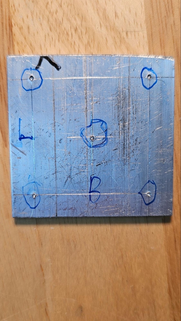
Using The Center Punch
There may be some temptation to jump to drilling out the holes as the centers are not marked where the lines cross one another. Drills have a tendency to wander when starting a hole, however, so it is helpful to mark the centers of holes with a center punch to provide a small dimple for the drill bit to sit in when starting the hole to prevent “walking.”
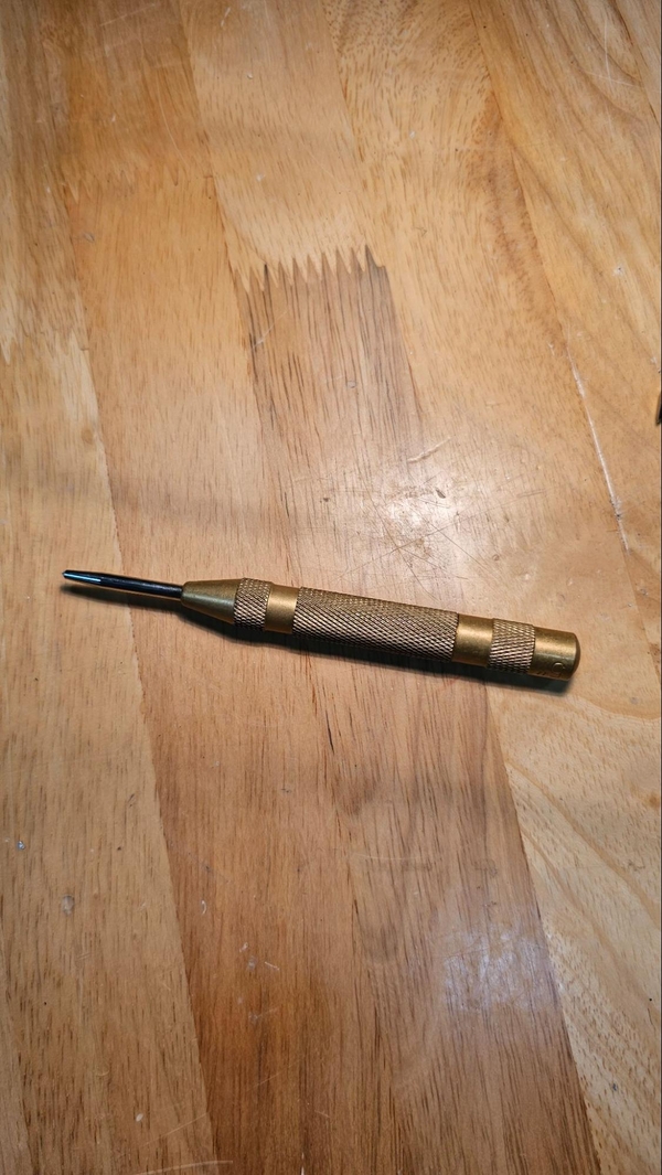
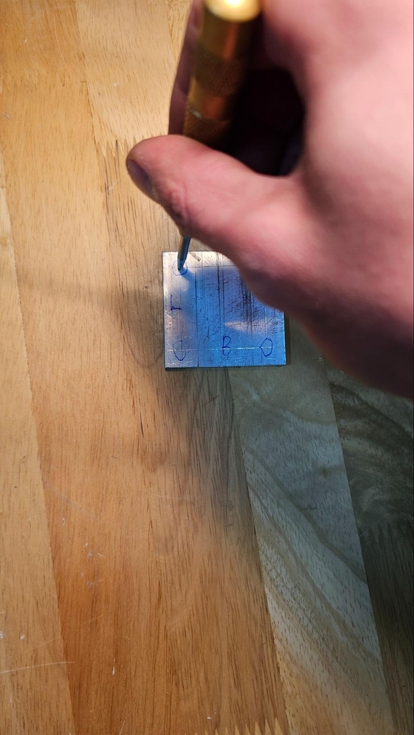
Some center punches require the usage of a hammer, while ones like the style pictured above are “automatic” and have an internal spring to slam themselves into the surface when pressed down. To line up the punch, follow the groves made by the calipers and press down to locate where the groves align. Make sure the punch is as straight up and down as possible when hammering or pressing down.
If you are not happy with the location of the punch mark, it can be hammered flat with a ball peen hammer or you can try angling the center punch and punching in the direction you want the hole shifted.
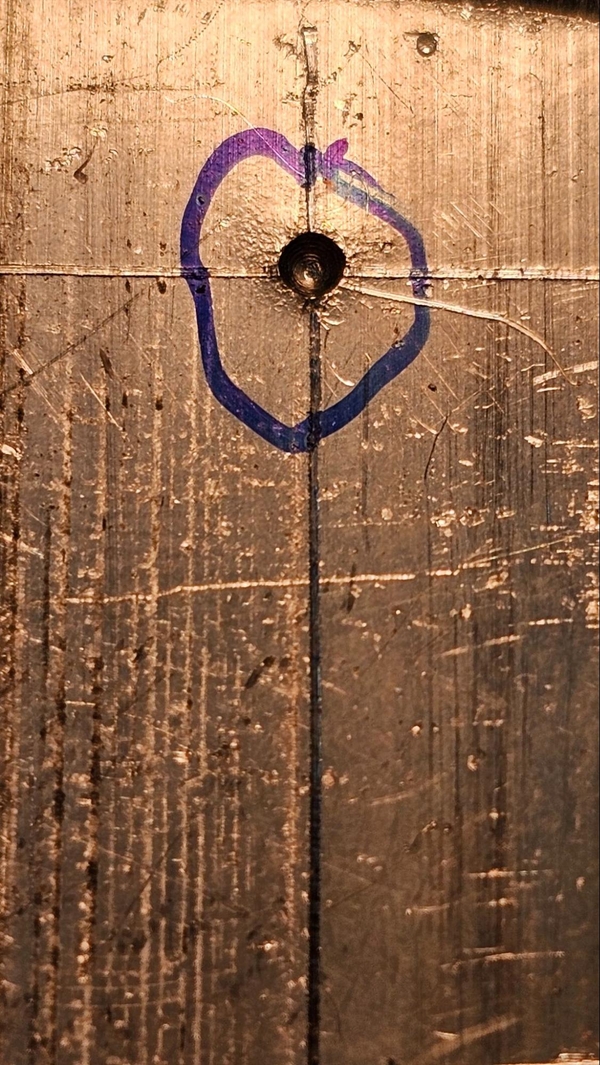
When finished your part should like this: