Drilling
Terminology
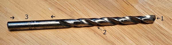
Twist Drill Bit
The most common type of drill bit. Some features to note:
- Tip or Point: The sharp point at the end of the drill bit (1)
- Flutes: Helical grooves which allow chips to exit the cut hole (2)
- Shank: The area where the drill will be grasped by a chuck (3)
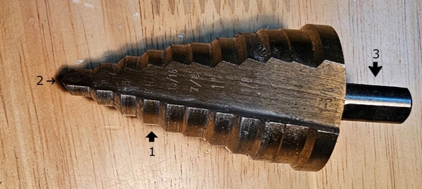
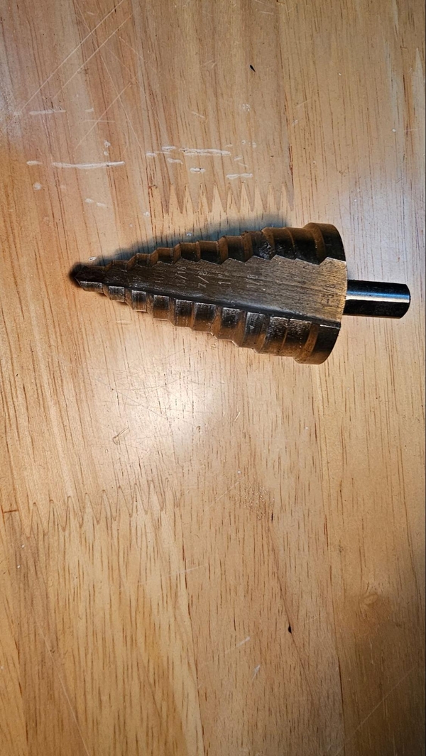
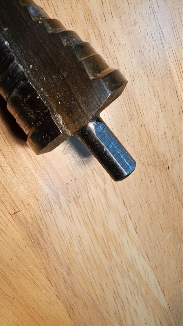
Step Drill Bit
A good option for creating larger holes. Features include:
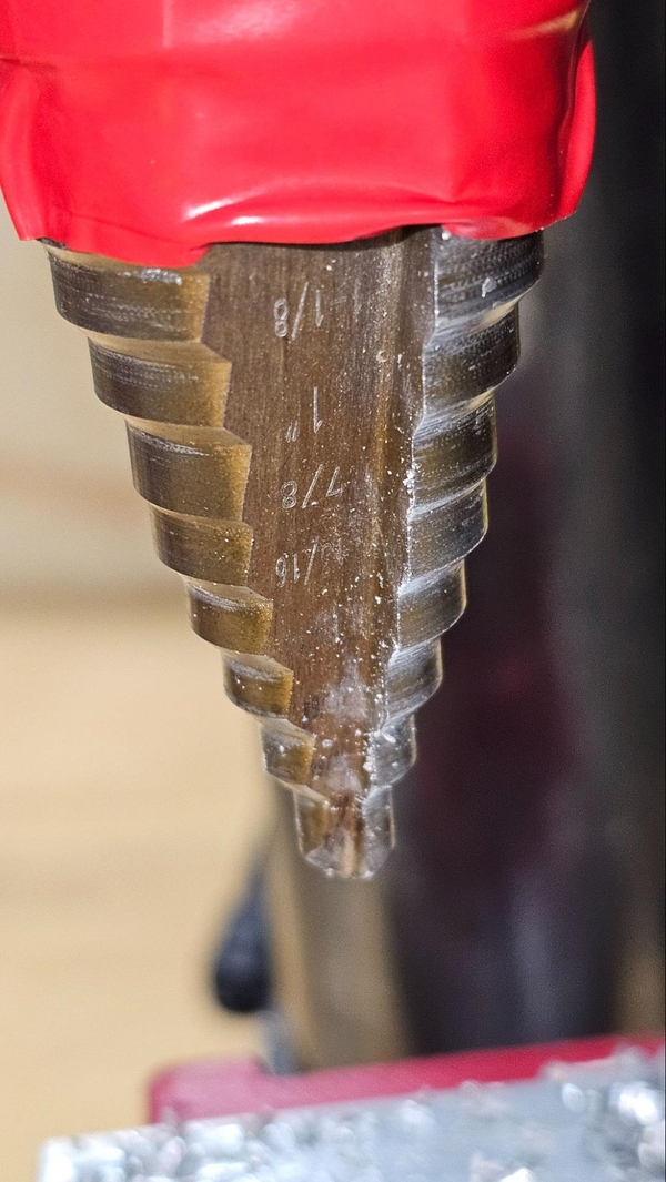
- Steps: Typically at 1/8" increments, they allow for the different sizes of holes (1)
- Tip or Point: The sharp point at the end of the drill bit (2)
- Shank: Area where the drill bit will be grasped, typically have flat and angled surfaces (3)
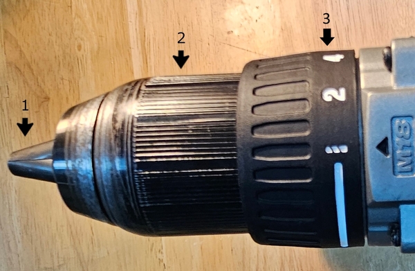
Keyless Chuck
Used to hold drill bits, the most common chuck on hand drills. Parts include:
-
Jaws: Typically three angled pieces that linearly move to grip the shank of a drill bit (1)
-
Body: Rotating this will cause the jaws to clamp or retract. Some ratchet to prevent loosening (2)
-
Clutch torque ring: Rotating this ring will adjust how much torque the drill can impart before its clutch begins to slip. Used more often for fasteners and should be set to the drill bit icon when drilling holes (3)
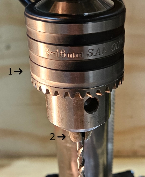
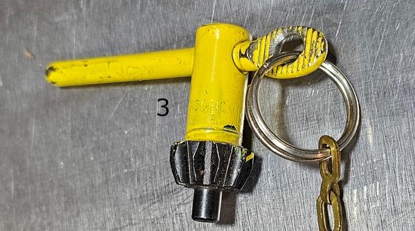
Keyed Chuck
Found on most drill presses, requires a chuck key to properly clamp the jaws onto a bit's shank.
- Body: Rotate by hand to prevent bit from escaping, then mate the chuck key with teeth to achieve proper tightness (1)
- Jaws: Similar to a hand drill, three angled pieces that clamp down onto the drill bit (2)
- Chuck Key: Used to properly tighten jaws. Attaching it to the drill press on a cable ensures it will not be lost (3)
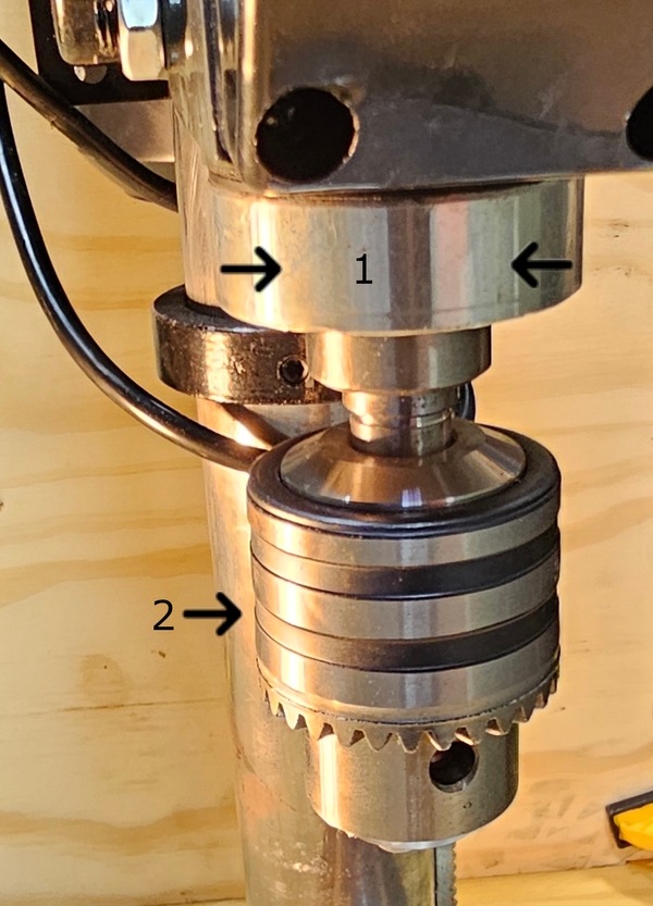
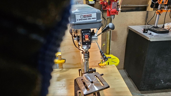
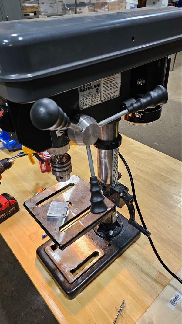
Drill Press
This machine is perhaps the most important tool for making a successful Everybot. This machine will have more torque, allow for more downward pressure, and create straighter holes than a hand drill.
- Spindle: Holds the chuck and rotates when motor is powered (1)
- Chuck: Almost always will be keyed (2)
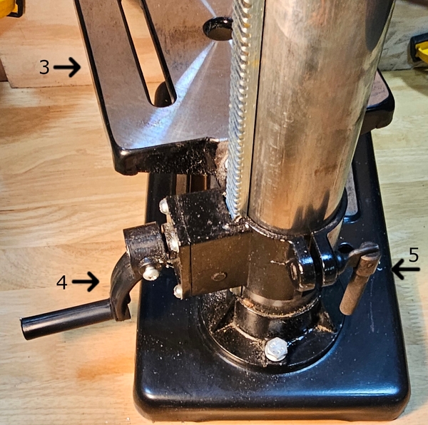
- Table: The surface that work will be held on. Make sure not to drill into it (3)
- Table Adjustment Handle: Move to adjust height of table (4)
- Table Lock: Unlock to rotate table around column or adjust height, always lock before drilling (5)
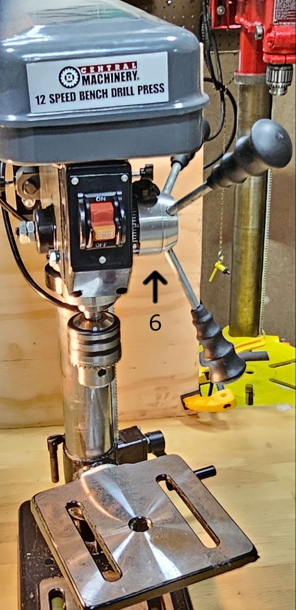
- Feed Wheel: Used to lower the spindle (6)
Hand Drilling
Hand drilling may feel safer than operating a large drill press but there is still a lot that can go wrong. Always wear safety glasses and make sure long hair is tied back.
Sometimes a hole requires you to support the rear of the work piece where the drill bit will be exiting. Make sure there is significant distance between where the drill bit will exit the piece and your hand. Experienced mentors have taken a drill to the hand from doing this, so avoid doing this at all and find a scrap piece of wood or other material that the work piece can be pushed up against instead of using your hand.
Parts that are not held down properly can aggressively rotate or be flung by a drill, and drill handles can rotate unexpectedly if the bit stalls in the hole, potentially wrenching your hand. A step drill bit can kick the drill or work piece really hard, especially if running at high speed on large holes.
Drilling by hand is great for any lower precision task. Holes that require higher precision can be done with a hand drill but thru holes will require more focus and skill to make sure the drill bit is not angled when drilling into the second surface.
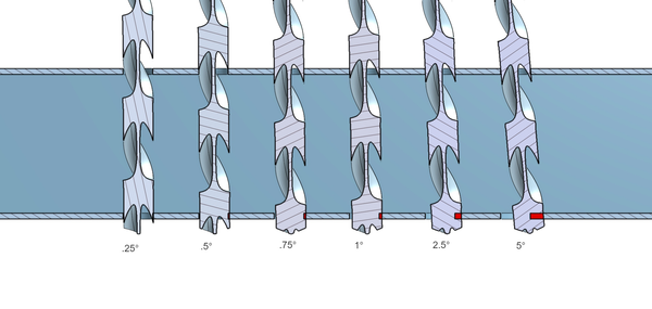
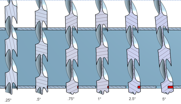
For a visual, here is a sectional view of a #7 drill bit (0.201" diameter) in a 0.201" hole at different levels of tilt. The drill bit is centered within the top hole and the red shows the undesired material that would be removed from the lower surface at different angles.
Drilling a hole
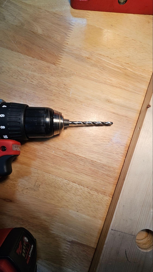
To start drilling a hole, a drill bit is needed. If the hole has a bit specified in the engineering drawing, try to use that one if possible. Start chucking the drill bit in the drill, making sure that the shank is firmly in the chuck with none of the flutes in the chuck. Tighten the chuck. Make sure the tip of the drill bit is concentric with the chuck (make sure it is centered and doesn’t wobble). If it does wobble it probably is off center and engaged with only 2 of the 3 chuck jaws.
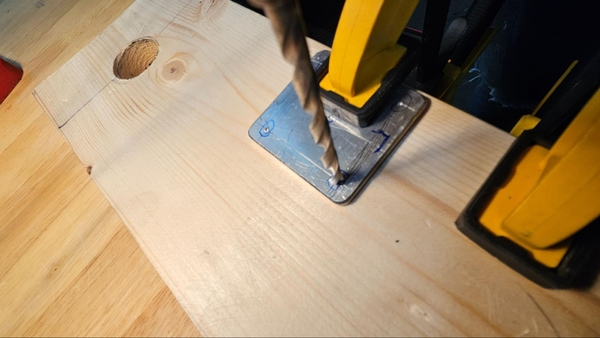
When drilling anything it is important to make sure that your part cannot move. Clamping the part to a table or using vice is typically recommended. Make sure that you will not drill into anything you do not want to. With a table this can be done by ensuring the drilling location is hanging off the table or by putting a sacrificial surface underneath it like wood. With a vise, wood with a width smaller or equal to the part also works but ideally a set of parallels designed for this purpose would be used.
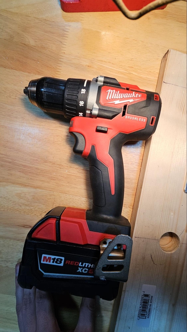
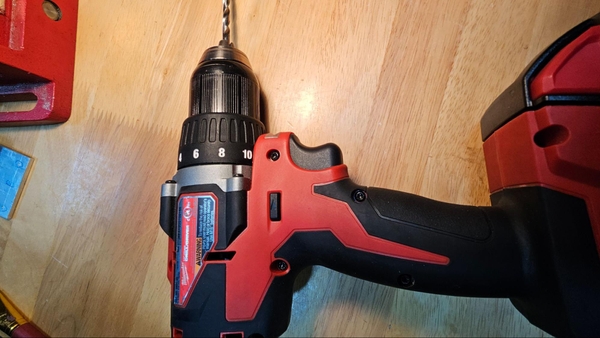
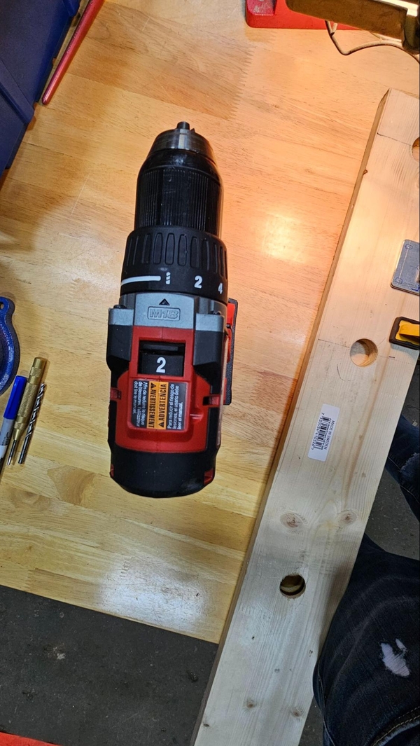
If your drill has a speed selector switch, set it to the faster “2” speed for most holes. For larger holes use the lower “1” speed. Make sure that there is no torque limiting by setting the clutch to drill, typically identified by a drill bit icon on the clutch ring. Finally, the drill needs to be set to rotate in the correct direction. A direction changer can typically be found on the side of the drill, with forward being the arrow that points towards the drill bit. This changer is typically a sliding switch with a forward button on one side and the reverse button on the other, with a neutral position in the middle. Pushing the button in on one side causes it to extend out further on the other, making it easy to feel which direction the drill is set to without looking once you learn which side is which.
If you have cutting fluid, apply some to the area of the hole. Center the drill in the center punch dimple, pull the trigger, and apply moderate pressure (the drill only spins, and without any force pushing it into the work piece it will not be able to drill down and through the material). Ensure the drill is straight as possible throughout the drilling.
It may be beneficial to have a friend or two help control the tilt of the drill to ensure straight holes in box tube. Be careful if inspecting a drill at eye level as chips can be thrown out and hair is more likely to be caught when up close to the drill bit.
When finished drilling, the hole will need to be filed or deburred to remove the rough edges around the hole. Use a file on the backside to remove the protruding material and then run a deburring tool around both sides of the holes to remove the burrs. Manually twisting a step or slightly larger twist drill bit in the hole may also work in place of a deburring tool, just be careful to not significantly enlarge the hole.
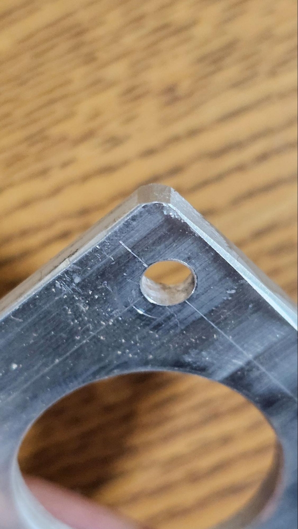
Hole needs deburring Improved hole
We will cover usage of a step drill bit with the drill press and would recommend a drill press for all holes that require it. If you only have a hand drill it can still be used, with operation nearly identical to the drill press, just make sure to set the drill to the lowest number speed and be prepared for the drill to catch and kick back against your hands.
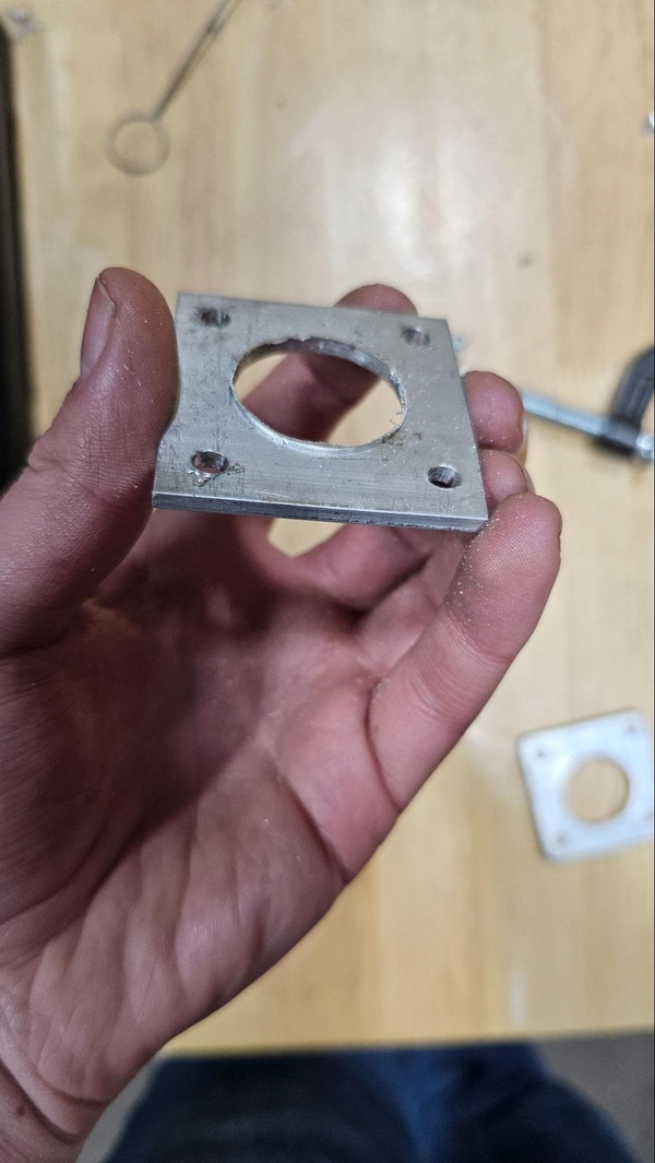
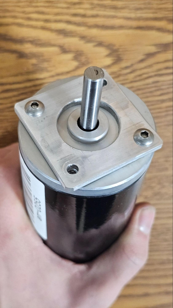
Hand Drilling Motor Plate Exercise
Taking guidance from the section above, drill out the 4 outer holes. Then drill a pilot hole in the center with one of the following drill bits: 1/8", 1/4" or #7. Check the diameter of your step bit's first stage, ideally use a drill bit for that size (typically 1/8").
When finished use a deburring tool plus a file on the holes. If there are mistakes don't worry, continue with the part. If all holes have been drilled go to the step bit section or make the same component on a drill press if you want to try out both methods to compare the results.
Drill Press
A Drill Press is a machine that will help make significantly straighter holes and make your machining more precise if used correctly. It will generally take more time to drill individual holes but the time is well worth the accuracy you can achieve.
To start using a drill press, ensure that it is in a safe state, with the power unplugged or the safety switch popped out. Open up the chuck by rotating it such that the jaws of the chuck move up and away from the center. When the jaws are able to fit your bit, place it inside and hand tighten the chuck. Make sure that a good amount of the shank is within the chuck and that the jaws are not touching the flutes of the drill bit.
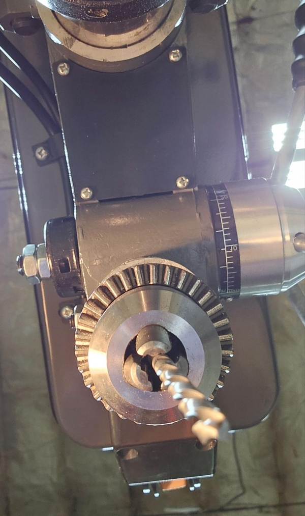
Jaws not properly holding shank Jaws are clamping onto flutes instead of shank
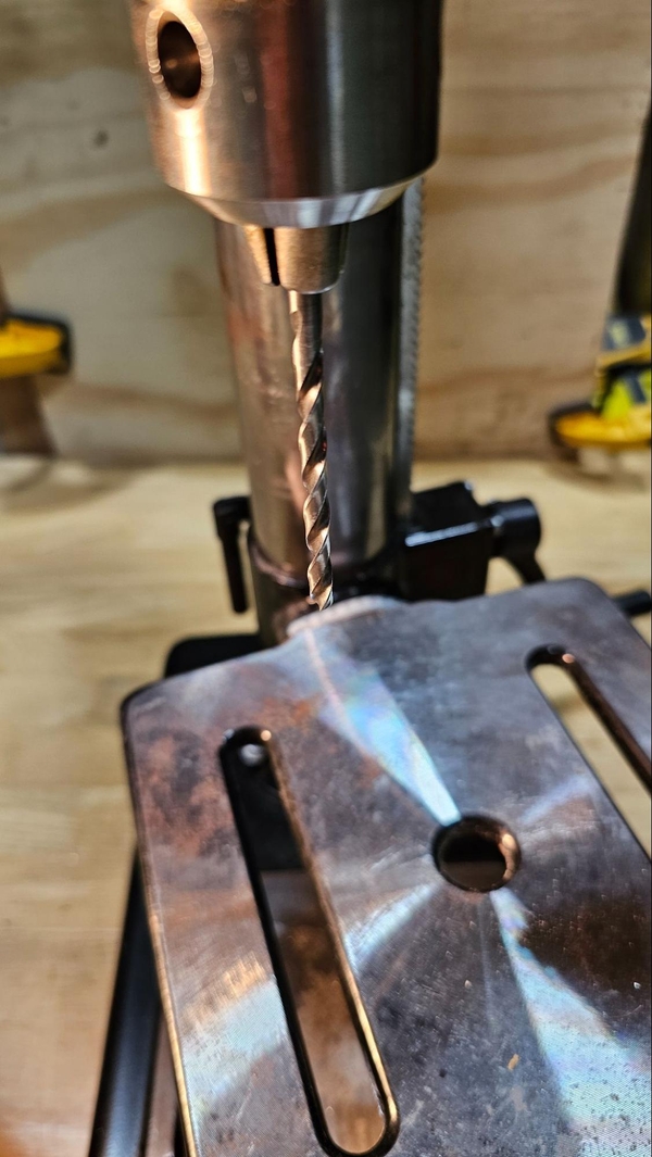
Once tightened enough by hand that the bit will not fall out, visually inspect it, make sure that all 3 jaws are making contact and that it does not angled or off center. If it is cockeyed, loosen the jaw and reseat it. When ready, use the chuck key to fully tighten the bit in place. Once tight in one location, rotate the spindle by hand and tighten the other 2 locations fully with the chuck key.
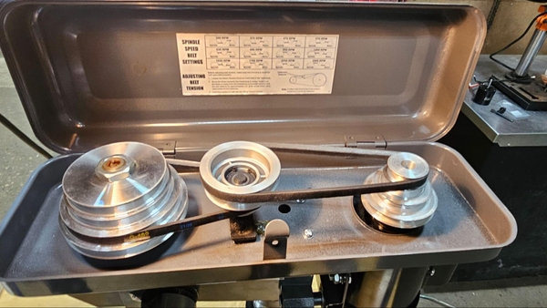
Next we will want to adjust the speed of the press. You may want to consult your manual but speeds between 2 and 3 thousand rotations per minute should work well for #7 drill bits with the recommendation being closer to 3k. This speed should be fine for anything under 1/4 of an inch thick.
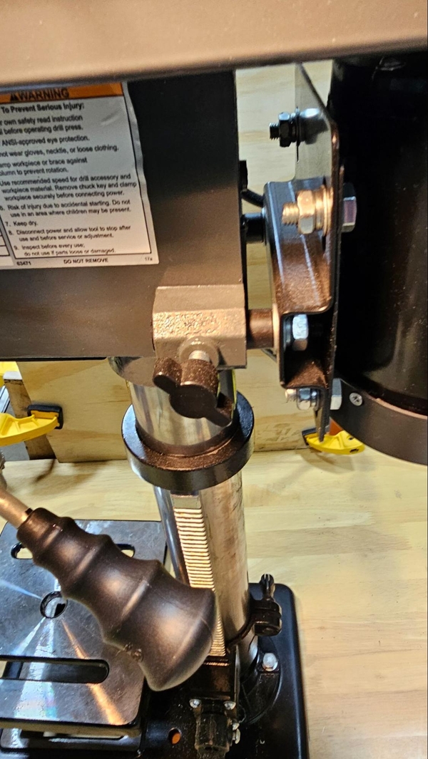
For drills that require manual adjustment, start by loosening the belt tension. This is typically done by loosening the thumb screws near the motor. It may be held in place on both sides. Move the belt to the desired pulleys. It may be easiest to pull the belt in the desired direction while spinning the pulley by hand. When done adjusting, make sure the belts are re-tensioned by fastening the motor away from the spindle. See your manual for specifics on the tension and adjustment of belts.
For drill presses that have an external speed adjustment wheel, typically the machine must be running for the adjustment to work properly. Turn the machine on and rotate the dial until it is set to the desired speed. Consult your manual for more details on your particular machine.
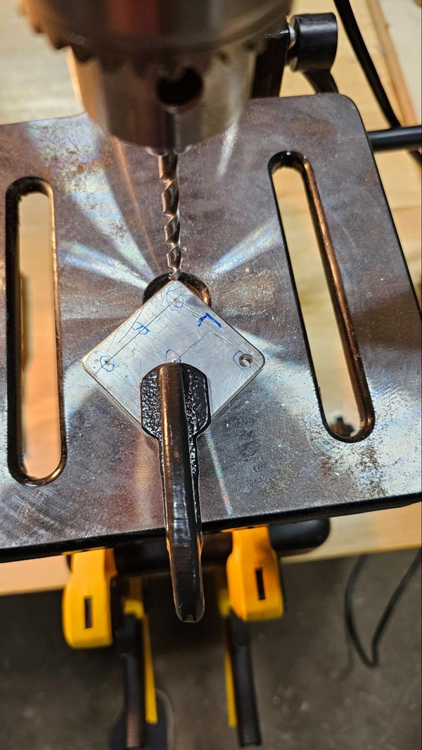
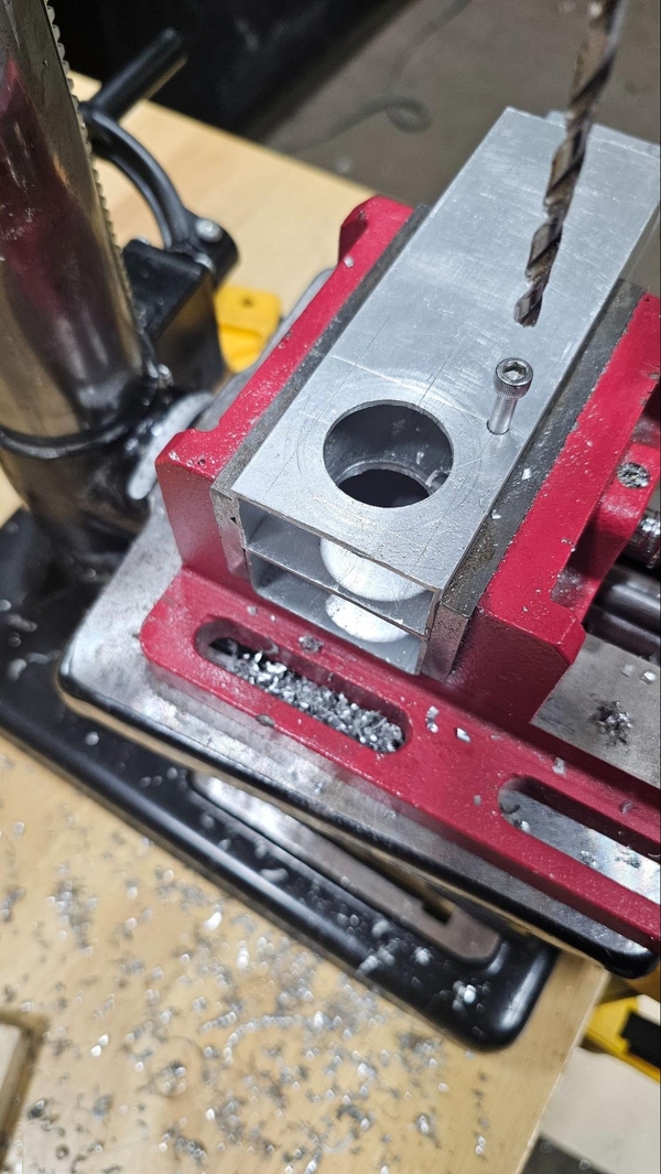
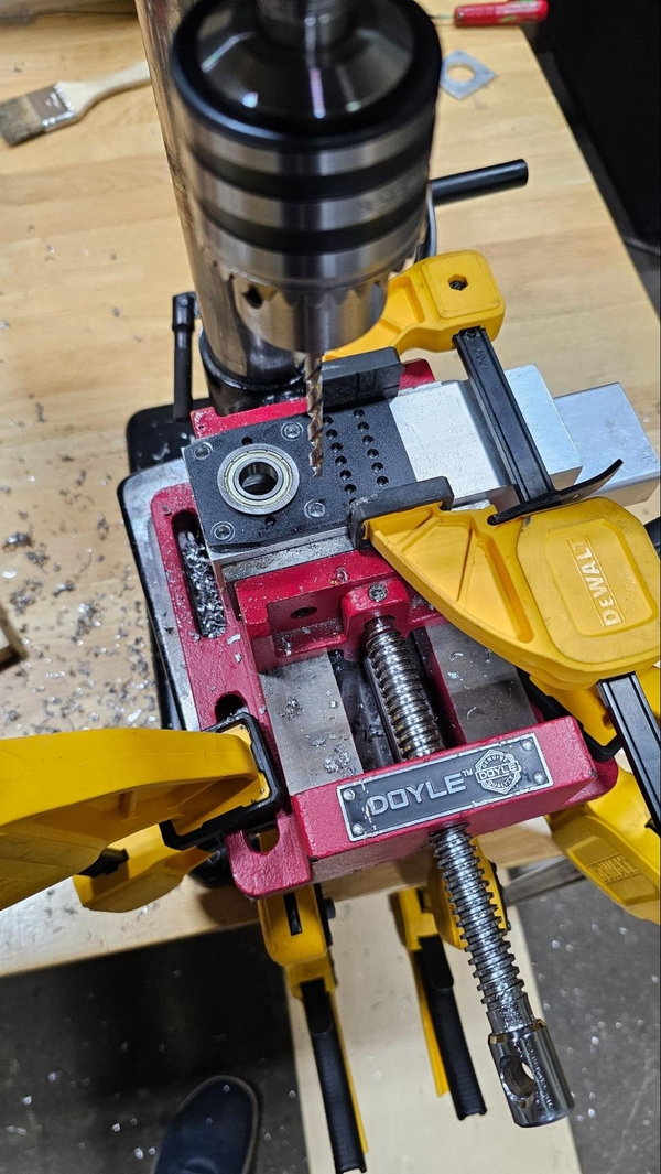
To safely drill into a component it must be properly affixed to the table. Clamping a plate directly to the table may prove challenging, especially in the center as the drill press may cause the part to flex into the hole as pressure is applied, causing the drilled hole to not be completely straight.
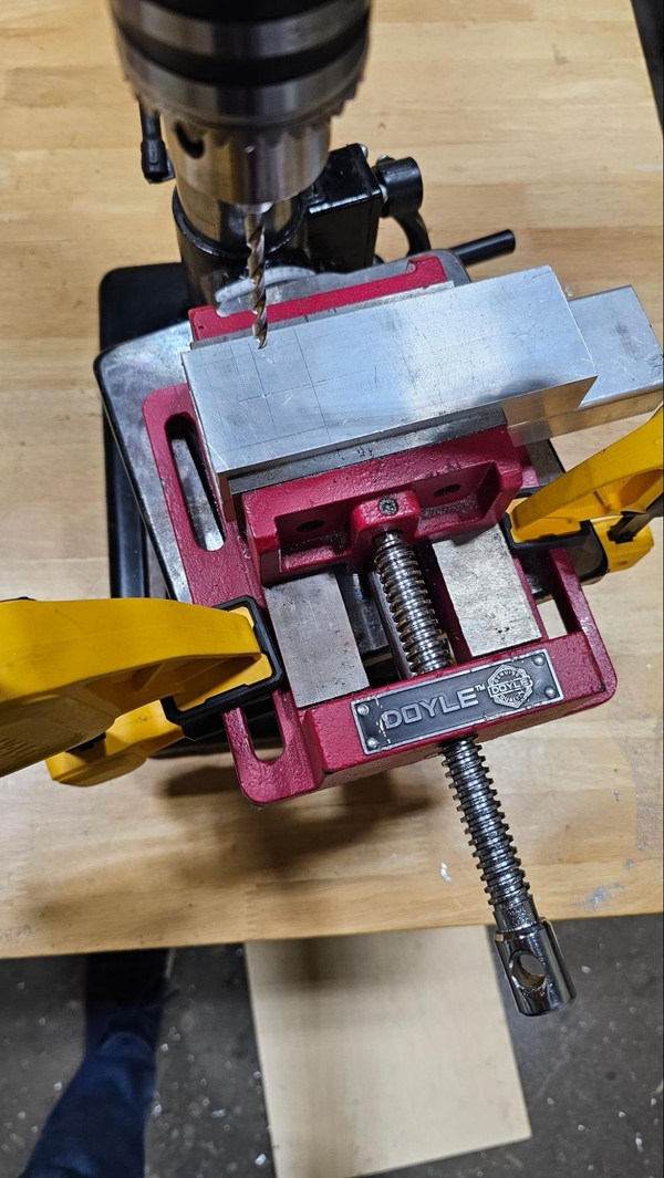
Using a vise clamped or bolted down to the drill press’s table will generally offer more support and can be more secure, especially if bolted down.
Make sure that you will not drill into the table or vise. Some machines have adjustable stops that will prevent the drill bit from being lowered too far, and tables will generally have a hole in the center to help prevent accidentally drilling through them. A piece of scrap wood can also be clamped under the work piece to prevent this.

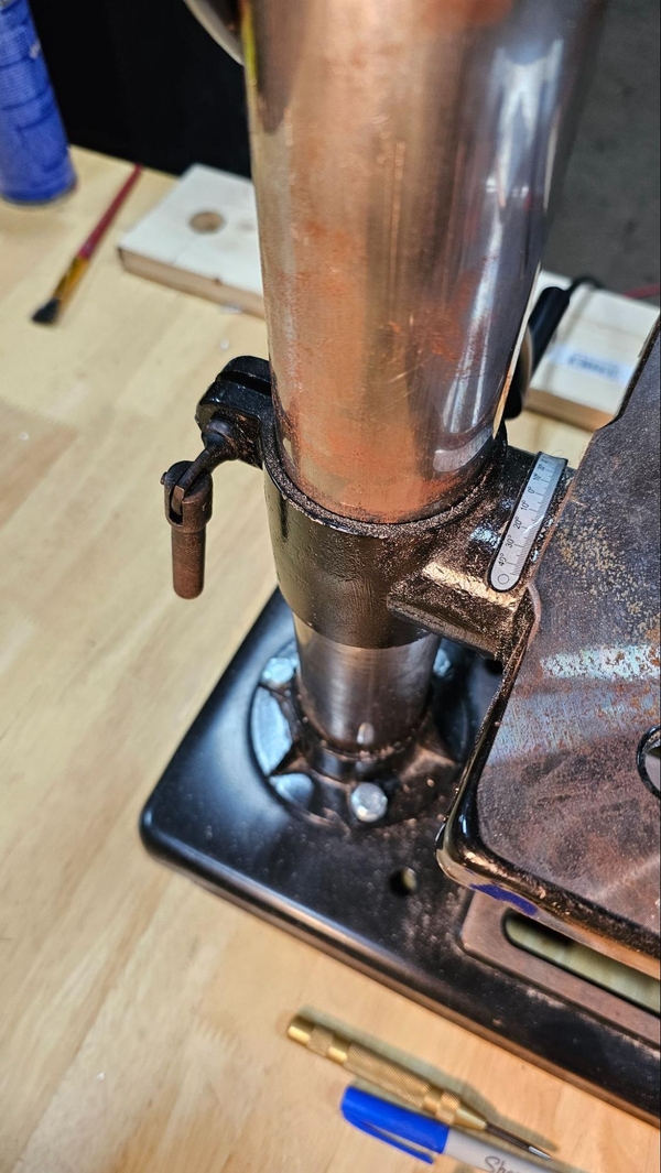
Once a clamping configuration is found you may find that the height and position of the table needs to be adjusted to properly make the hole. If the drill bit is already below the surface of the work part or the feed wheel does not allow the drill bit to reach low enough to cut entirely through the part, the table will need to be adjusted down (in the first case) or up (in the second case). A locking mechanism on the rear or side of where the table is attached to the neck of the drill press can be undone and the table can then be cranked or slid up and down the neck. When adjusting the height, always make sure that the final movement of the table is at least a slight upward movement as this will prevent backlash pushing the table down slightly. When done, lock the table back in place.
Finally, position the part so the drill bit is roughly centered over the center punch dimple. Lower the drill press (still turned off) onto the dimple paying special attention to the drill bit. If the drill bit deflects to one side to get into the dimple, meaning the drill bit moves slightly at an angle to enter the hole, then you are not centered. Continually peck with the drill bit until you find that the drill bit does not deflect. Clamp the part down in this location, ensuring that it does not shift. Some drill presses will have a laser alignment feature to help line up the bit, but this may need to be calibrated and should still be double-checked by lowering the bit down into the punched dimple.
This process can be annoying but it is important to get it right. To make the process easier, if you find that you like the alignment in a certain direction you can place a clamp against that edge of the part. This will not lock the part down but you can press the part against the clamp to ensure you have that axis of movement “correct.” This can be done twice before clamping the part down, ensuring it does not shift when clamping.
Another good technique is to keep the part loose and peck until the drill bit does not deflect into the dimple. With the tip of the bit in the dimple, add a clamp, not lifting the bit until the piece is clamped.
When clamped, pull the bit down to the surface once more, ensure that the holes line up and that the clamps will not interfere with the handle or cutting process. At this point the drill press can be powered on to ensure that the drill bit is concentric with the collet. Look at the point of the drill bit, it should not oscillate left or right (a tiny amount may occur with some cheaper or older presses). Power off the press then ensure that the peck is still centered within the divet.
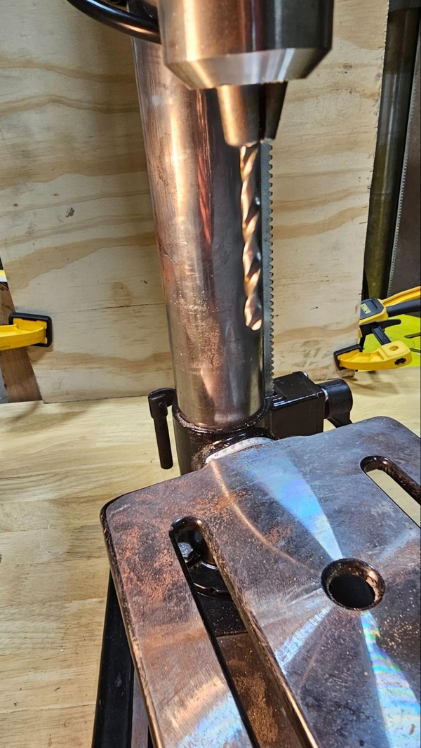
You are now ready to make the hole. Put some cutting fluid on the part around the area to be drilled. Power on the drill press lower into the part. You will need to apply light to moderate pressure to get the bit to cut down into the material. If not enough force is applied the drill bit will not make progress in cutting the hole and will begin to heat up. Too much force can cause the drill to stall or also heat up. If you are using sacrificial material under the piece you will be able to feel a difference in the resistance in the feed wheel and the chips being ejected by the bit’s flutes will also change. Rotate the feed wheel back up (do not simply release it, as this will cause the drill to slam back upwards quickly) and then turn the machine off and allow it to come to a complete stop.
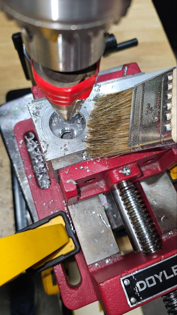
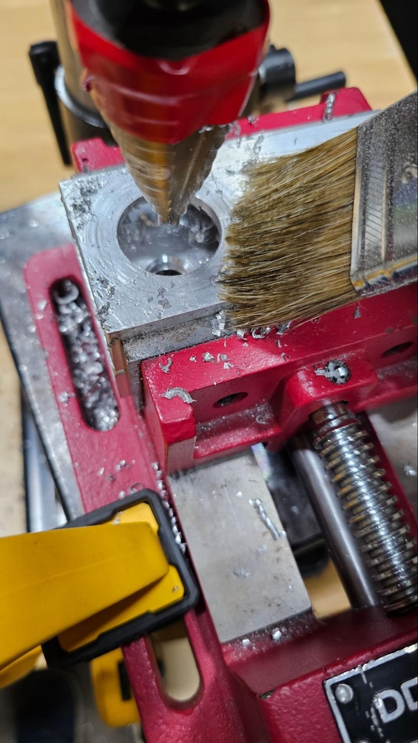
When done, make sure not handle the aluminum chips as they could be hot and will be sharp. These can be vacuumed up or be swept with a chip brush. The hole will need to be filed and deburred. Using a file on the backside to remove the protruding material and then run a deburring tool around both sides of the hole to smooth out the rims.
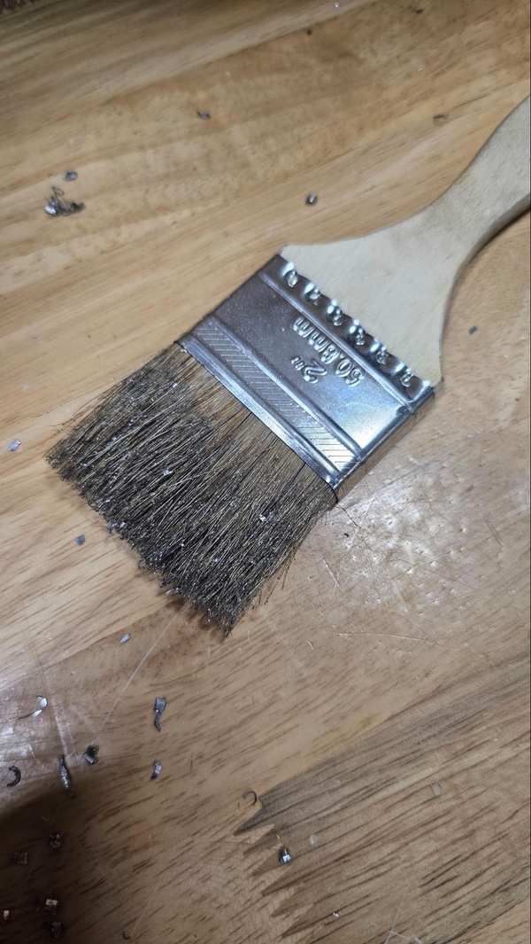

Chip Brush Hole that needs deburring
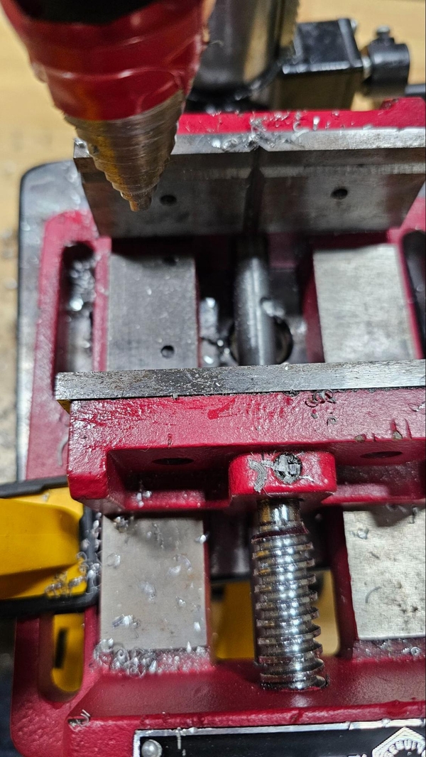
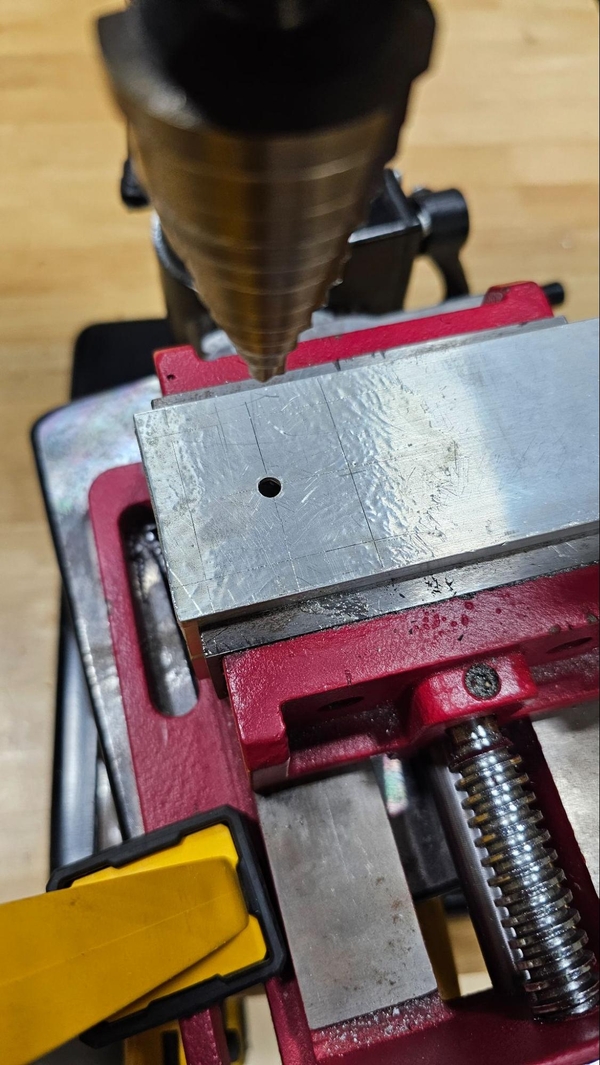
Step Drill
In FRC, Step Drills are a decent option whenever a bearing hole or other larger hole needs to be drilled. Step drills can also be used to widen existing holes.
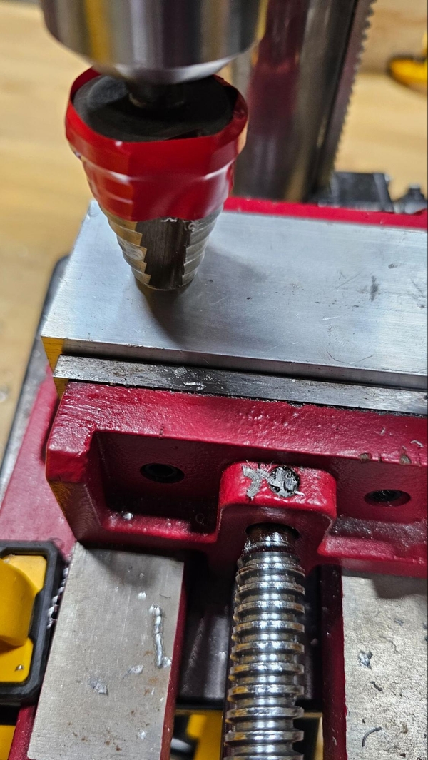
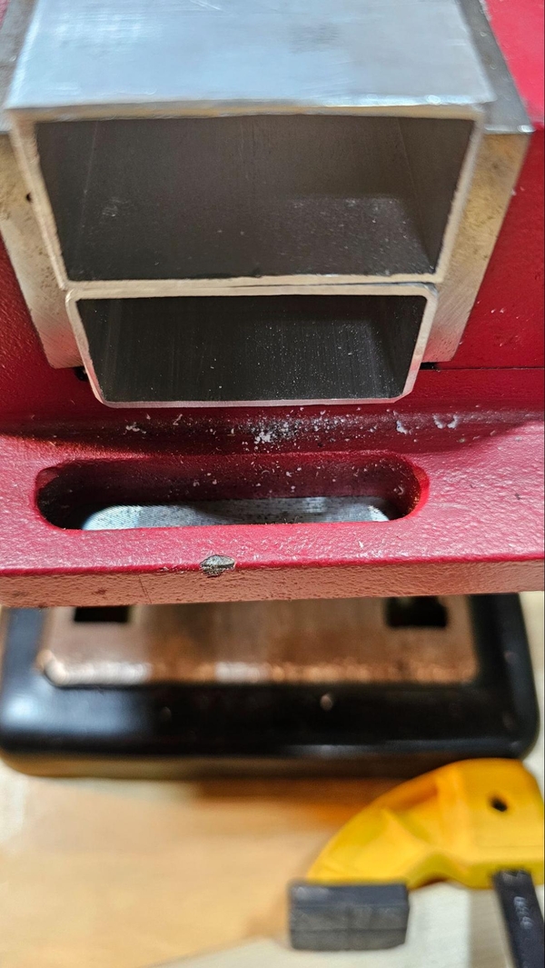
When using a step drill bit for tube stock you will need to be mindful of how much of the bit will end up poking through the other side of the material. You will want a drill press vise that has room for the step drill bit to have clearance on the other side, generally by clamping the work piece towards the top of the vice’s jaws with a set of parallels or another sacrificial piece of box tube or wood underneath it that the bit can drill into. Keep in mind that bit will also likely produce a smaller hole in the opposite face from the one you are drilling into, which may not necessarily be used or will need to be flipped over and widened out to match the hole on the other face.
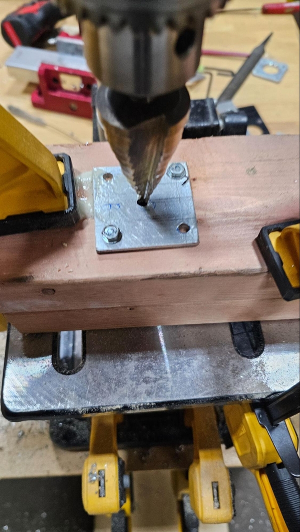
If drilling something flat, you will need a piece of wood that is thick enough for your step bit to drill into, which could be up to 3 or so inches depending on the bit and the size of the hole being drilled. If you plan on using wood over a vise, please see the tab below.
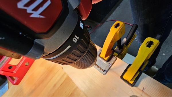
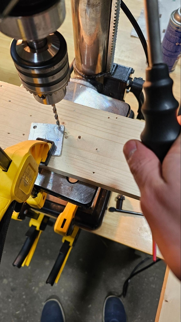
If using wood you will want to create a hole in the desired cutting location before cutting the aluminum (more on this later). A drill press is preferred for step bits but a hand drill can be used at its slow speed. Expect the bit to want to catch and kick the drill back in your hands, so make sure you clamp the piece down well and hold the drill securely so that if it does kick it will not wrench the drill out of your hands or hit other parts of your body.

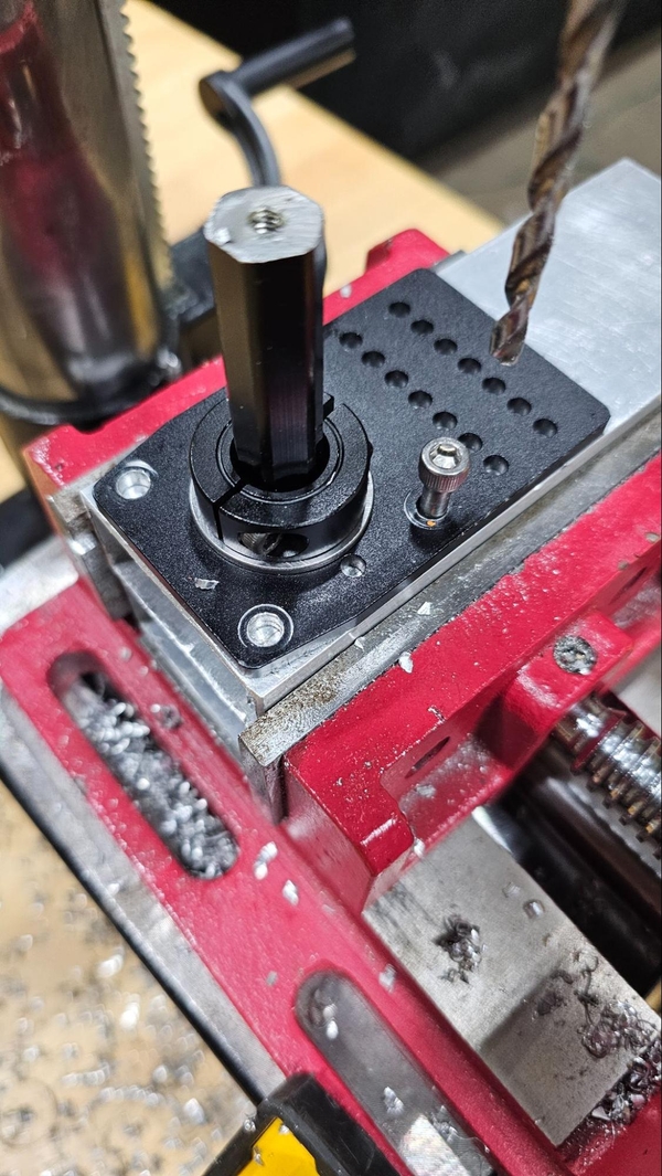
Once a workholding technique has been chosen you will need to chuck the step bit into the drill. Put the drill bit in the collet, making sure to use the chuck key to tighten it down in all 3 holes. Note that you may not be able to chuck the step drill all the way into the machine as the shank might have an angled surface when it meets the steps. Additionally, some step drill bits (and some normal bits as well) may have alternating rounded and flat surfaces on the shank. Make sure the chuck is gripping onto the flat surfaces and not the rounded portions.
To use a step bit with the drill press you first need to change the speed of the drill press. Typically the lowest speed is best.
A note on positioning wood
Most drill press tables do not have holes large enough to prevent a step bit from drilling into them when making larger holes. This can be avoided by adding more wood underneath the piece, putting wood under the component in a vise that has clearance for the step drill bit, or drilling slightly off the edge of the table (not recommended).
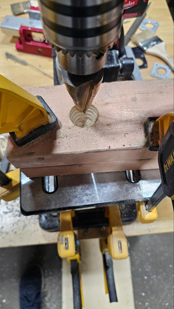
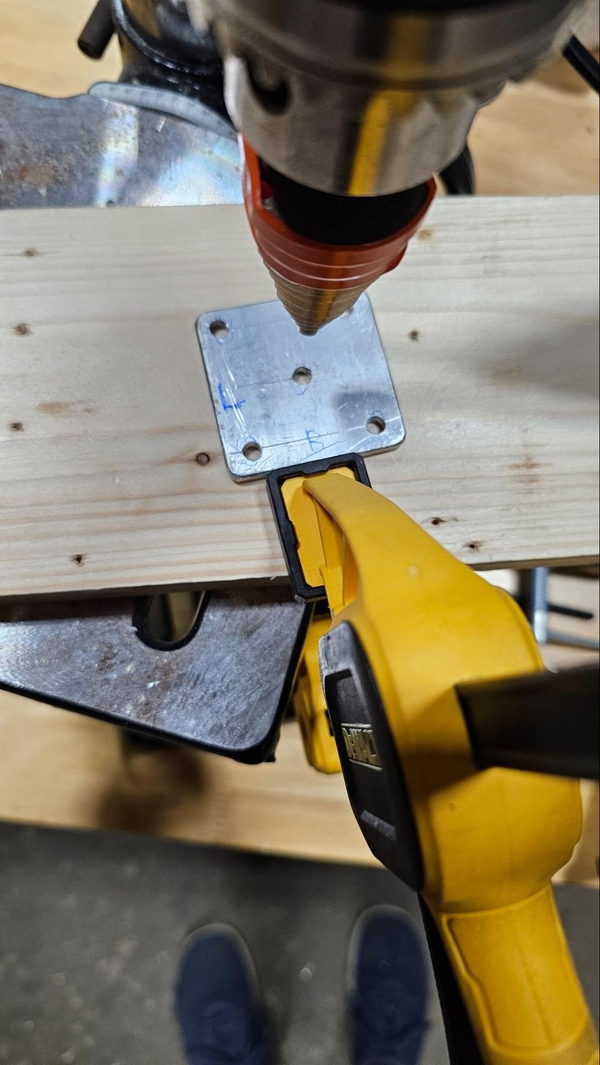
After securing the wood to the table, apply cutting fluid to the bit or wood. When ready, power on the drill press and plunge into the wood. If the bit does not make progress for a bit, back it out, turn it off, and see what is wrong. Wood can easily clog the flutes of the step bit and cause excess heat and smoke. A teammate can hold the hose of a shop vacuum to constantly clear chips (being careful to not position their hands close to the bit). A pilot hole through the whole wood stack will allow for chips to leave more easily, reducing the buildup of heat and shavings. If you need to stop early due to clearance you may be able to flip the wood over and finish the hole on the other side. Generally for this application, the max size of the step drill bit will work well.
Put your workholding method + part into the machine, unlock the table, adjust the table height and position for your configuration, making sure your last vertical operation is upwards. Lock the table in place.
To keep track of how deep to lower the bit to cut the desired size of hole, a strip of electrical tape can be applied so that it covers the steps larger than the desired hole size, making it obvious where to stop drilling down when the bit is rotating and the size markings can not be read. Be sure to leave the flutes of the bit uncovered so they can still eject the chips produced as it drills.
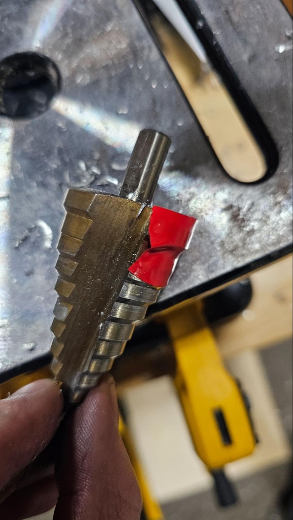
Good tape Tape blocks the flutes
Some images below may show the tape blocking the flutes. This is done for visual clarity and should not be imitated.
Start lining up the part. Similar to a normal bit, “peck” the bit down into the marked dimple to ensure it is lined up. Power on the drill and ensure that the bit is not significantly moving from side to side as it rotates, and power it back off. Ensure you are still centered in your hole. Apply a generous amount of cutting fluid to the part, power on the machine and begin drilling down, moving slowly through the different steps.
You will need to use more downward force for this operation than a normal twist drill. If you see smoke during the operation, bring the bit back up, stop the machine, and assess the situation. DO NOT TOUCH ANYTHING, as the smoke is a sign that there is significant heat being generated and the parts will likely be extremely hot. Is the machine running at its slowest speed? Is the bit dull or are the flutes clogged? Is there enough cutting fluid? Are you trying to drill through the material too quickly or with too much force?
If there are a lot of metal shavings building up, stop the machine, use a brush to get rid of the chips, apply more fluid and continue. Also check both flutes for gummy chips as they can stick to the bit, especially when soaked in cutting fluid.
When the hole is the desired size, be careful as the aluminum and step drill bit will probably be very hot. Give the component some time to cool and touch it lightly to ensure it is handleable before fully picking it up.
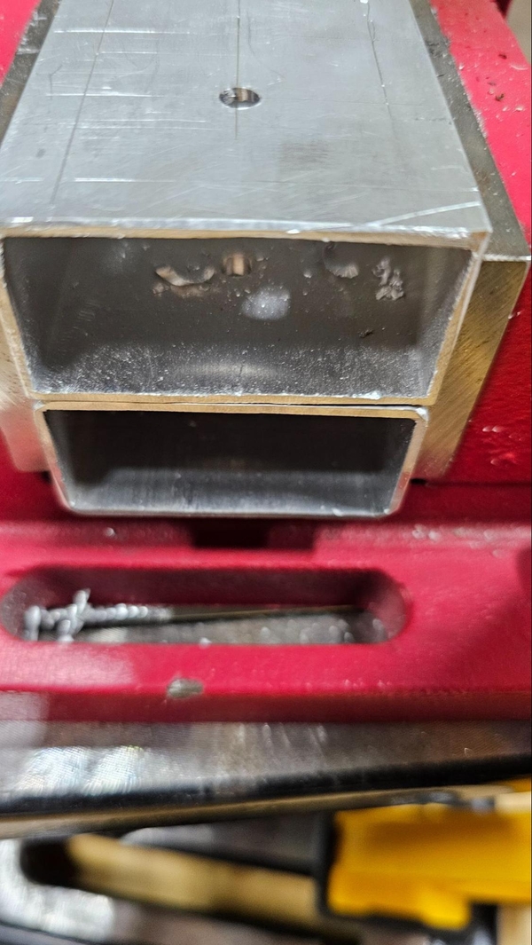
If you are making a through hole, you will need to slip the part over to drill out the other side to be larger, as continuing to drill down will widen the hole in the top face. Reaffix the component in the vise and bring the step drill bit down low enough that the step that matches the size of the smaller hole sits snugly inside it, lining up the rest of the bit to produce a straight through thru hole.
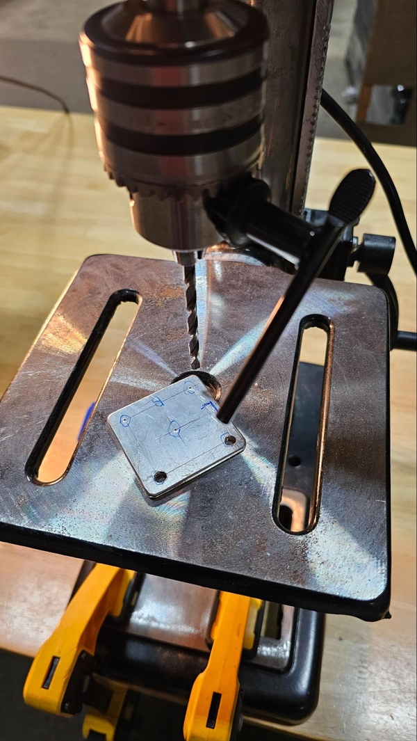
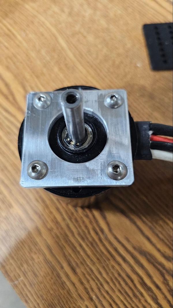
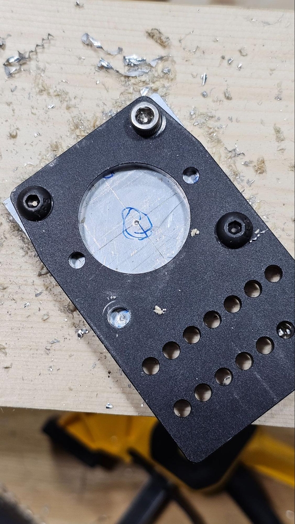
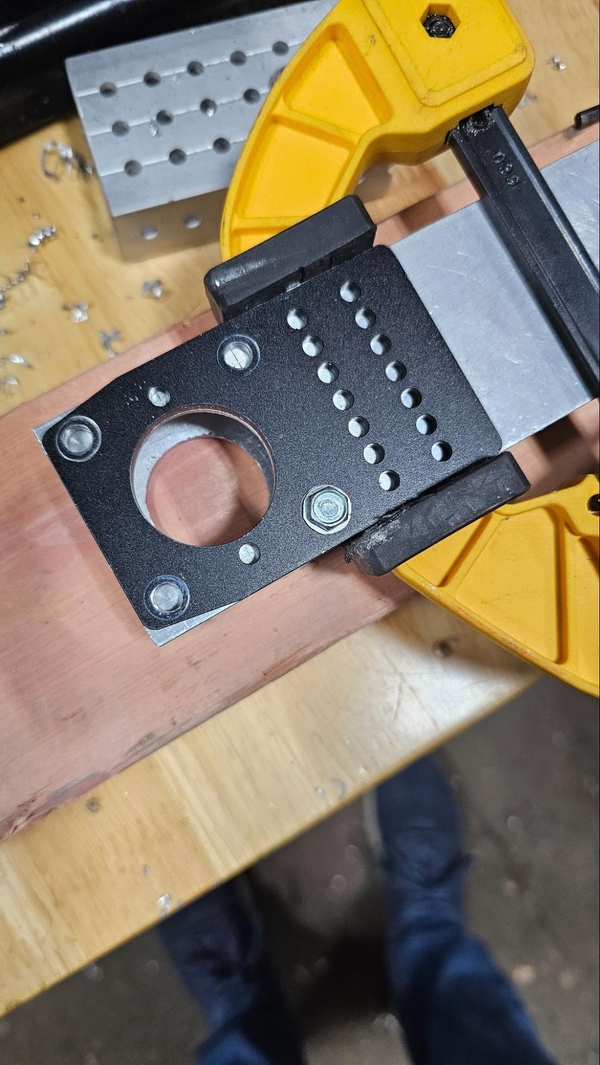
If you have been following along with the example part, now is the time to test it. Take some 10-32 bolts and see if you can get two bolts through your CIM. If you have a NEO motor you can try to see if you can fit all four. Make sure that the bolts go in straight - if the holes are offset slightly this can cause the bolts to go into the motor at an angle and cross-thread the motor mounting holes, which you do not want to do as it will make it hard or impossible to properly mount the motor safely and securely.
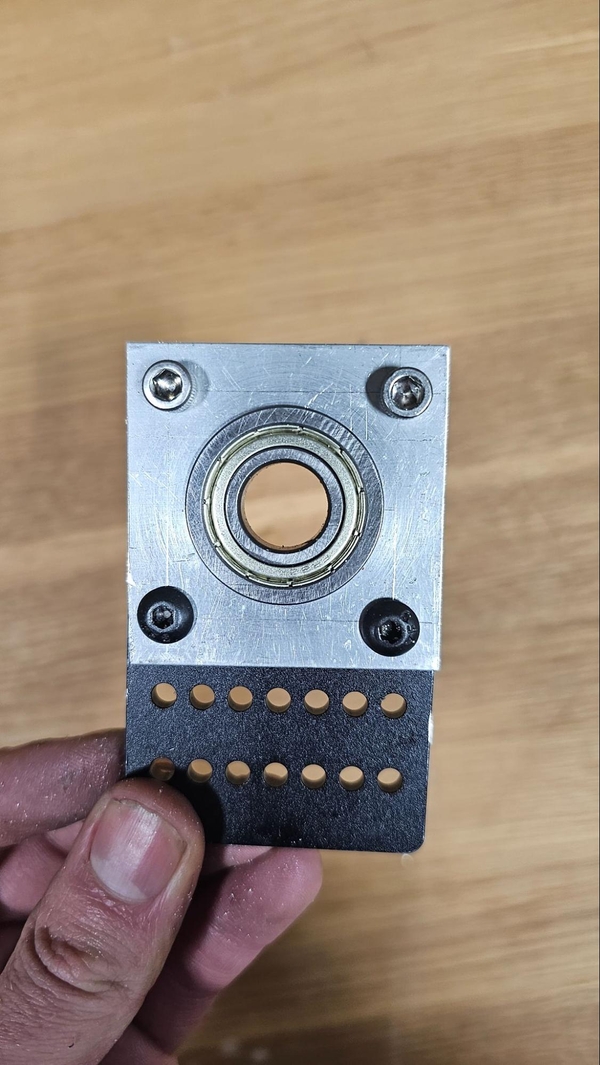
If you have a bearing plate with the same hole pattern you can see if the four bolt holes and the bearing hole all line up. The pictured plate is the Thrifty Bot Bearing Megaplate.
This is a fairly difficult challenge, especially for people new to machining, so don’t worry if you messed it up. Feel free to try again if you have time but know there may be an easier way.
Match Drilling
Match drilling is a drilling operation wherein holes are drilled through multiple stacked components at once, with the goal of ensuring that the holes line up perfectly between the two pieces. If you were trying to draw a circle by hand, a stencil would help to make the circle more accurate, and similar techniques can be used to drill holes. If you need to drill out holes to mount a bracket or plate and the bracket can be clamped down on top of the work piece, the holes can be drilled into the work piece thorough the holes in the bracket to ensure they will line up.
This also works well when you need identical or mirrored parts by match drilling through both components at the same time.
Generally match drilling is best done with a drill press. When drilling deep holes through a tall stackup with a drill bit, it can be difficult to ensure a hole is straight the longer the distance gets. Additionally, the drill bit may not be long enough to make it through all faces, requiring a second drilling operation. It will take more time on a drill press but the increase in accuracy will help mitigate the compounding errors that can occur.
Here are some general tips for match drilling:
-
If match drilling with an off-the-shelf item, try to use a drill press. Even though it seems quick and easy to use a hand drill, you can accidentally widen the template’s hole. This is especially true when drilling into box tube, as a small angle to the bit will produce a large offset of the lower hole due to the distance between the two faces.
-
When using a template it is important to make sure it stays in the same location the whole time (or at least when it matters). This can be done by solidly clamping the template component in place where the clamp will not need to be moved to drill all the holes. Bolts can also be placed down through the holes that have already been drilled to hold the two pieces in place
-
If match drilling occurs between two pieces of tube stock that must be identical, make sure to line them on one end only.Think about what you will be attaching the tube stock to and align the parts on the end that will be attached to the more “solid” component (for example, the side that will be attached to the chassis versus having a mechanism or more superstructure attached. It is best if this side is a factory edge, as filled edges may not be as easy to line up.
A few examples of match drilling operations:
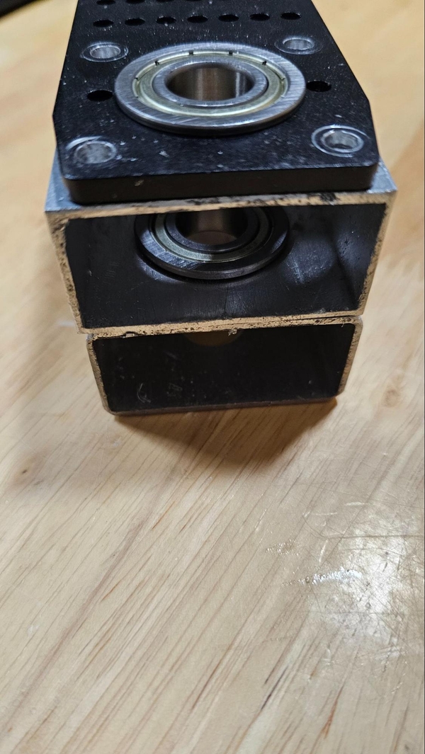
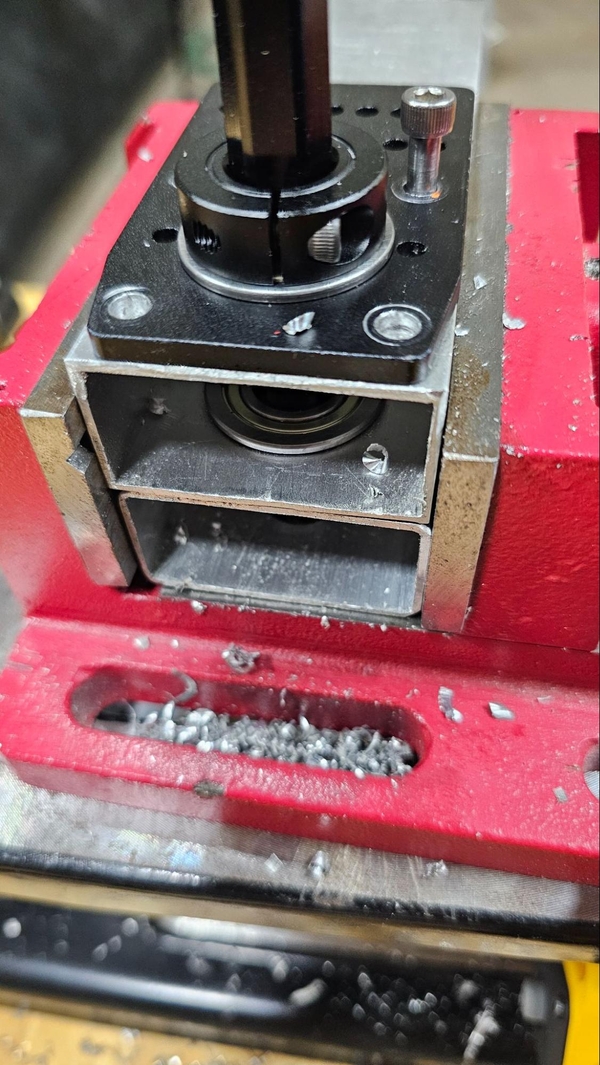
Attaching a Bearing Plate to Tube Stock
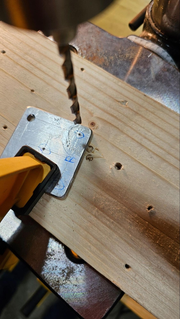
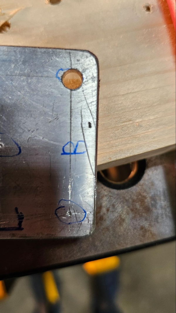
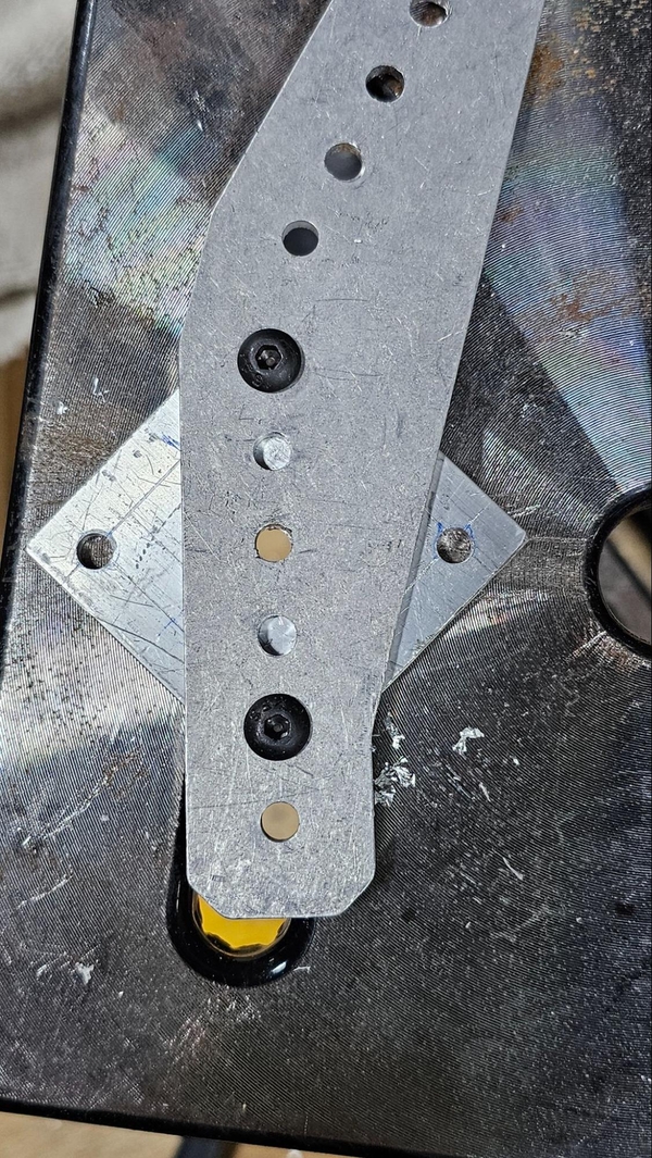
A drill press is highly recommended. As with all cutting and drilling operations it is best to still scribe and punch the location of every hole. Start by making the large bearing holes by match drilling a pilot hole down through both faces of the tube stock in the center of the bearing hole and then using a step drill to drill both sides out individually to the desired bearing hole size. The bearing hole is done first because it is hard if not impossible to line a large step drill bit up with the center of a large area like the bearing hole in the plate. Instead, the bearing hole will be used to index the two pieces off of one another to ensure that the smaller mounting holes can be match drilled to line up properly.
Put the plate over the bearing hole and insert a bearing to prevent the two pieces from shifting relative to each other. If possible, use a clamp or put some shaft through the bearing to hold it down so it cannot pop out while drilling the other holes. Also use clamps to prevent the bearing plate from rotating on the tube stock, especially if the rotational position of the bracket is important.
Then drill out the other mounting holes that you plan on using. Putting a bolt through the drilled-out holes will also help keep the two components aligned.
Bolt plus hex shaft weight Wood screw in rightmost hole
Attaching Bearing Plates to Identical Pieces of Tube Stock
Cut the two pieces of tube stock down to length and scribe and punch the center of the bearing holes. Align the tube stock preferably along factory edges on the side of the tube stock that will be attached to the chassis or other larger, static component. Clamp them together or on top of eachother in a vise.
Start the operation by drilling the pilot hole for the bearing. The length of most drill bits will often only be enough to drill through the three upper faces of the two pieces, leaving the bottom face of the lower piece undrilled. Remove the upper piece of tube stock and drill down through the hole in the lower piece’s top face, through the other side and out the bottom.
Using a step drill, drill the pilot holes on all four faces out to the desired diameter of the bearing.

Because bearing holes on identical superstructure components will usually need to line up along distances with hex shaft running through them, small misalignments can cause the shaft to bind or be cockeyed. If this error is too great the parts may need to be redone. If you have the other components necessary, checking this alignment now by inserting bearings into the holes, holding them at the appropriate distance apart, and placing the shaft through the bearings to see if it is angled or binding. If the holes are significantly misaligned, you will probably want to remake the offending part rather than bother to drill out the rest of the templated holes and put a subpar component onto your competition robot.
Similar to the single tube stock method above, align the bearing plate using a bearing on the top tube stock and clamp the whole stackup into a vice. If you are producing mirrored components with the bearing plates being mounted off center from the axis of symmetry instead of identical ones (or mirrored components with bearing plates that are centered along the axis of symmetry) and the mirrored features (I.E. and angled cut or off-center hole elsewhere on the piece) are already in place, make sure the that one of the pieces is flipped relative to the other. Drill down through the desired holes with the appropriate bit.
If you are unable to drill through all four walls, three should suffice as the top tube stock can be removed, the plate repositioned on top of the lower tube stock, and the drill used to drill down through the remaining face.
You should now have two identical pieces of tube stock with hole patterns matching the bearing plates on both sides.