Kitbot Chassis
This section of the documentation is intended to aid teams that have little or no experience with the Kit of Parts chassis or those that are having problems following the AndyMark instructions.
Chassis Type
The AndyMark AM14U5 chassis is part of the Kit of Parts and is well-tested and reliable. The included 6 inch rubber treaded wheels have good traction with the field carpet and the center wheel is 1/8” lower than the front and rear wheels to make it easier for the robot to turn on the spot and make small adjustments when trying to pick up and score game pieces (this is called a “drop center” drive because the center wheel is dropped down slightly).
Chassis Size
The AndyMark “long” chassis configuration has plenty of room to mount mechanisms and electronics.
Chassis Cuts and Tools
Required tools:
- 1/4” socket and ratchet (preferred) or flat blade screwdriver or bit
- 1/2” wrench
- 9/16” wrenches or sockets
- 7/16” or similar size socket
- 3/8” socket or ratchet
- 5/32” allen wrench or t-handle
- Bandsaw or chop saw
Adjustable wrenches can be used in place of the 9/16” and 1/2” wrenches
A cordless drill and 10-32 tap are optional but can make assembly faster and easier
All required parts for the chassis are from the AndyMark AM14U5 Kit of Parts chassis box except for four CIM (or CIM-replacement) motors. Two CIM motors are included in the standard Kit of Parts, with four additional CIMs included in the Rookie Kit of Parts. The chassis assembly section of the manual refers to Andymark part numbers, so keeping the Andymark manual open to the parts checklist may help you when following this manual.
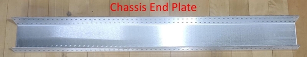
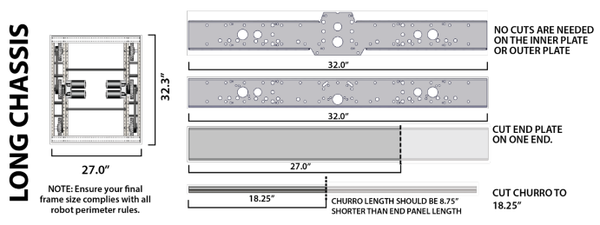
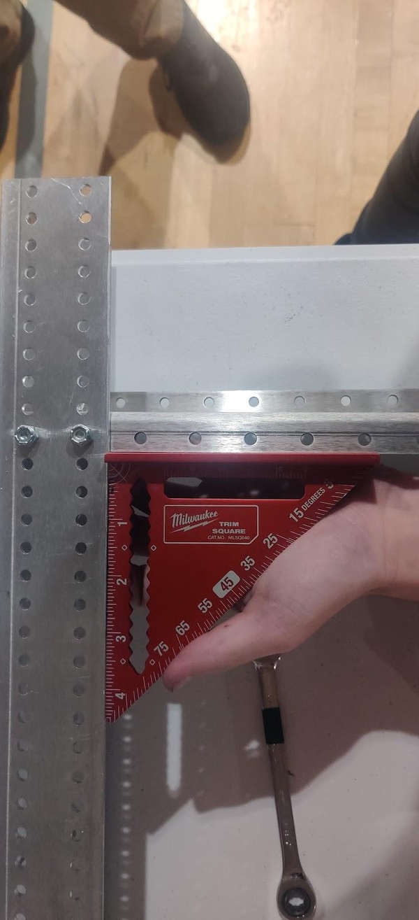
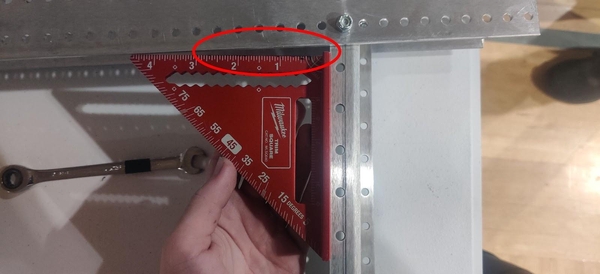
Before beginning to assemble the chassis, the two Chassis End Plates will need to be cut down to 27” by removing 4” from one end. The two 24” churros will need to be cut down to 18.25”. If the size of your team allows for it, have someone begin making these cuts while another group begins assembling the wheels. Measure out your cuts and mark them with a combination square to make sure your cuts are perpendicular and cut the plates in a bandsaw or chop saw, making sure to account for the width of your blade. Save the end plate cutoffs for later.
Wheel Assembly
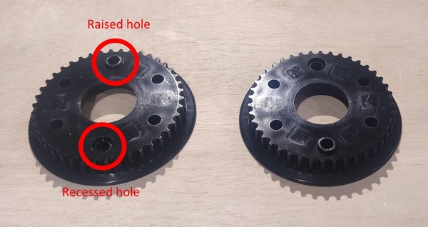
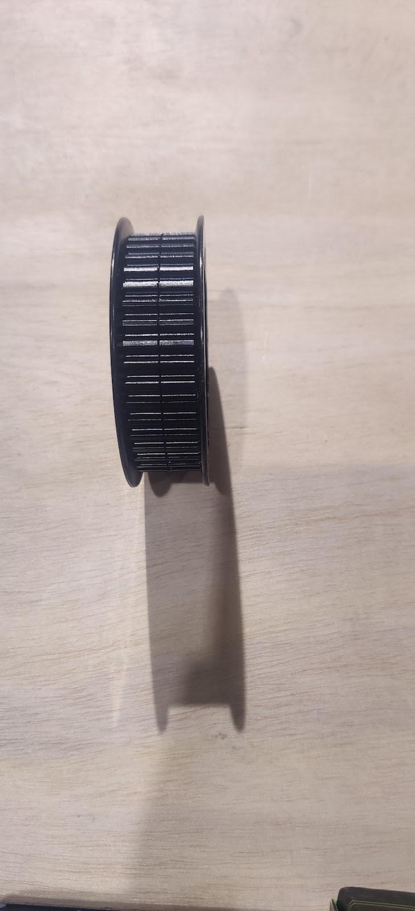
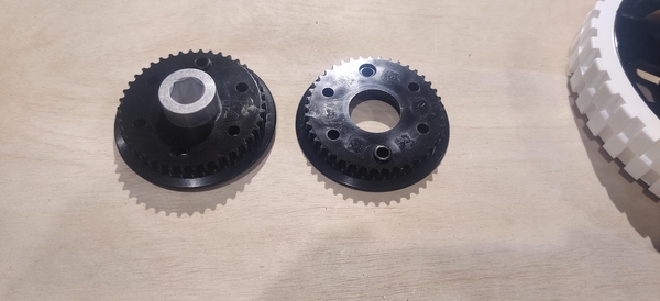
Start assembling the wheels by screwing two pulley halves into one side of each wheel. Each half-pulley (AndyMark part number am-2234a-half) has one raised screw hole and one recessed screw hole on the bottom. Connect two halves together by lining the raised portion of one half with the recessed hole on the other. The ridged portion of the pulley that the belt will actually ride on should line up across the two pulleys with no gaps or misaligned teeth.
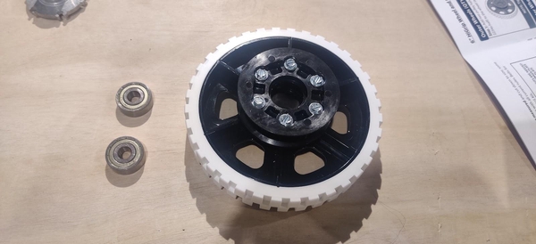
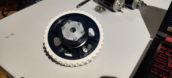
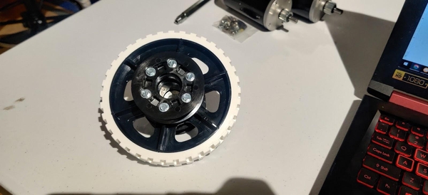
The pulley is then screwed into the matching hole pattern on one side of the 6” HiGrip wheel (am-0940b) using six 10-12 1.5” screws (am-1654). Tighten these bolts in a star pattern like you would when changing a tire on a car to ensure the pulley is aligned evenly on the wheel.

A 1/4” socket driver is preferred over a flat bladed screwdriver for fully tightening these form-threading screws as they will need more force applied to them in order to cut away the plastic hub of the wheel. The socket driver does need to be somewhat thin-walled, as a large driver will foul on the pulley before the screws are fully tightened. A ratcheting driver or a drill will also make the process much faster.
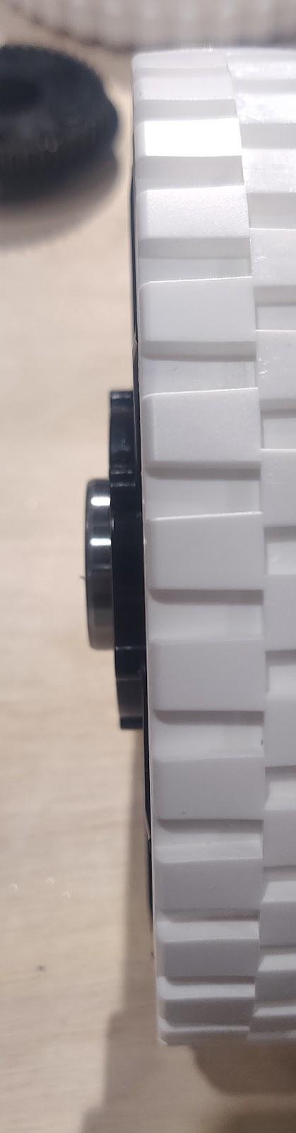
Four of the wheels will have two 1614ZZ 3/8” round inner diameter bearings (AndyMark part number am-0209) pushed into either side. One bearing will push into the open center of the pulley and the other will push into the open center of the wheel. Do not hammer or otherwise harshly strike the sides of the bearings to push them into place as this can easily damage the bearing. The bag that these bearings come in contains two bearings with a flange - a raised ridge around one of the outside edges. Set these bearings aside for later.
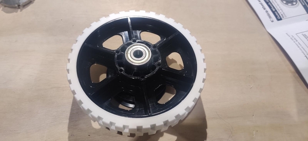
One easy way to make sure they are seated correctly is to line the wheel up on top of the bearing on a table and push the wheel down firmly until the bearing slips into place. The bearings will stick out of the bare half of the wheel slightly and be flush with the top of the pulley. These will be the front and back wheels of the robot.
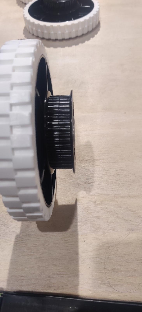
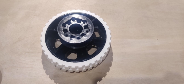
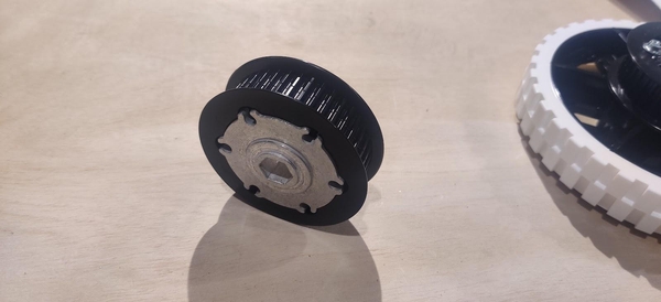
The other two wheels will have one of the remaining pulleys added to the other side with a 1/2” hex hub inserted inside it. The easiest way to line up the hub is to insert one half of a pulley onto the hub’s shaft and line up the screw holes in the hub with the screw holes in the pulley by putting a few of the form-threading screws through the hub and pulley. Push the other half of the pulley down to meet it, matching up the raised and recessed holes as before.
The 1.5” screws included in the 2024 Kit of Parts collide with one another when tightening them into both sides. AndyMark suggests simply continuing to screw them in, pushing the tips of the screws to either side of one another. This may be somewhat hard to do by hand, especially with a flathead screwdriver. If you have wheels from a previous year you may want to take the shorter screws out of them and insert them into the fresh wheels instead. Avoid reusing competition-used wheels as they will probably be worn down and less grippy than fresh wheels.
Motor and Gearbox Assembly
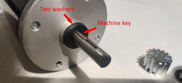
For each of your four drivetrain motors, place two 5/16” washers (am-1009a) onto the shaft. If your team is a rookie team, your kit of parts should include six CIM motors. If you are not a rookie team, your kit will contain only two CIM motors, so you will need to purchase two new motors or reuse two from a previous year (recommended). Two more CIM motors are also used in the KitBot launcher mechanism if your team plans on building it. Install a machine key into the slot in the motor shaft.
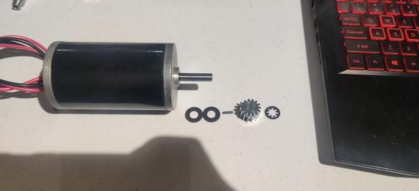
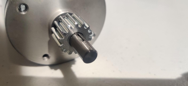
Slide a 14 tooth pinion gear (am-0034) onto the motor shaft, lining up the key with the gear’s keyway. Clip the stackup onto the motor shaft using an 8mm retaining clip (am-0033) with the teeth of the clip pointing inwards. Do not push the clip fully down against the gear or it can cause the motor to bind.
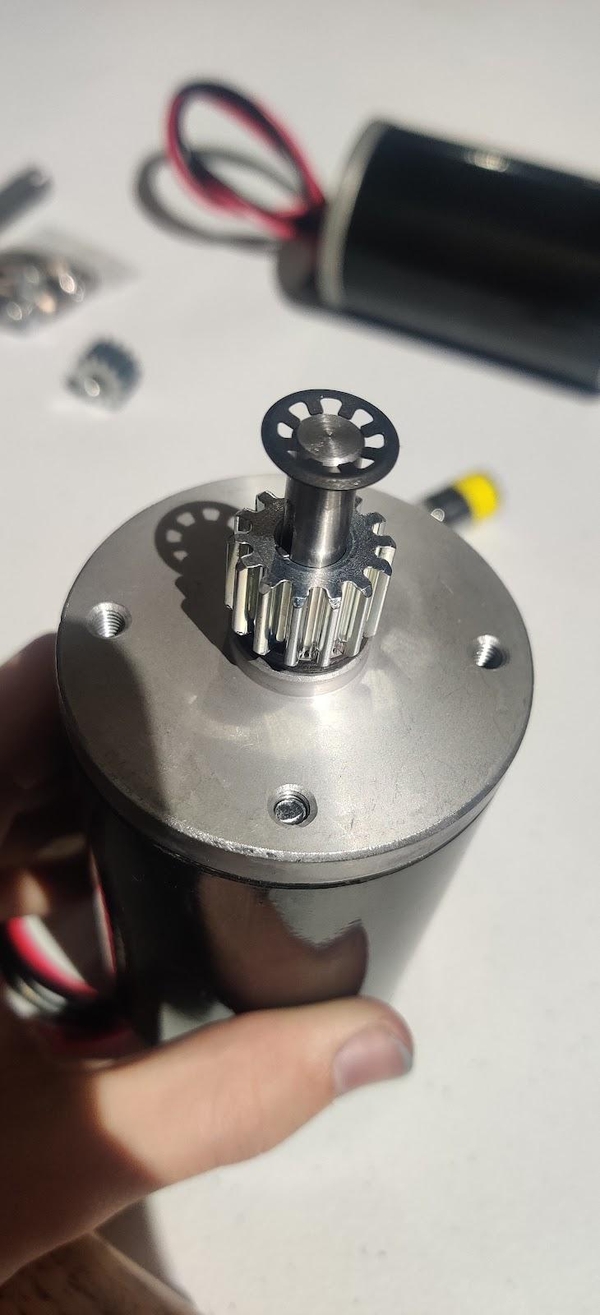
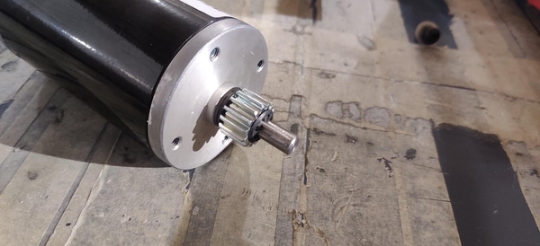
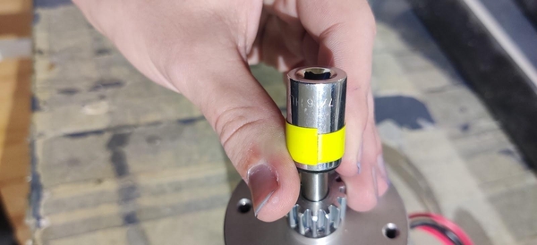
Placing a 7/16” or 3/8” socket over the clip and hitting it with a mallet can assist in pushing the clip down onto the shaft. This can be fairly difficult to do, and if the clip becomes deformed you should try to flatten it back out.
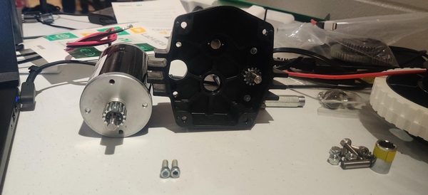
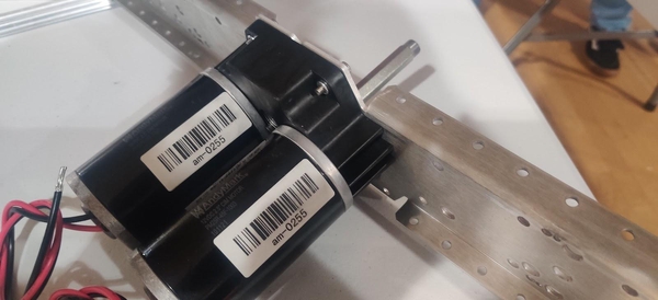
Screw two of the motors into each Toughbox Mini S gearbox housing (am-0650). The output shafts of the motors line up with the two larger holes in the gearbox housing and are screwed in using 10-32 x 0.625” bolts with thread lock already applied (am-1120) through the mounting holes above and below the input shafts and into the two mounting holes in the face of the motor. As these bolts approach fully tightened they become harder to turn. Make sure the bolts are actually fully tightened or the CIM motors will flex and rock around in the gearbox. If you can wiggle the CIM motors by hand then they need to be tightened more.
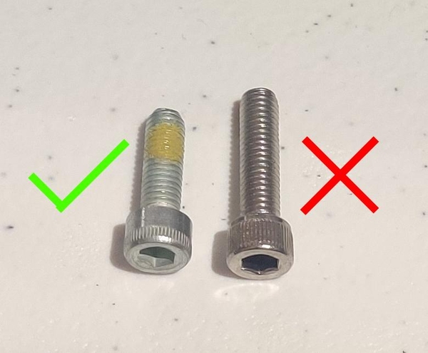
These bolts can be identified easily by the small patch of yellow or white thread lock on the threads of the bolt. Threadlocker is used on these bolts so that the motors do not vibrate them free over time. They are also shorter than the 10-32 x 0.75” bolts that come in the same bag.
CIMs have four holes in the face of the motor. Two already have long cross-head screws inserted from the bottom of the motor to hold them together, so you may have to rotate the CIM motors around until the two open holes line up with the mounting holes in the gearbox housing.
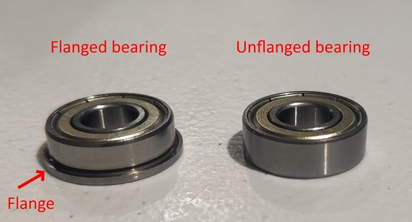
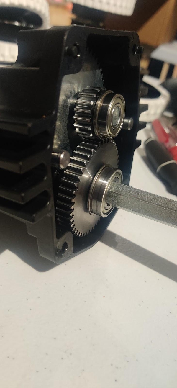
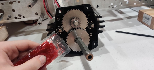
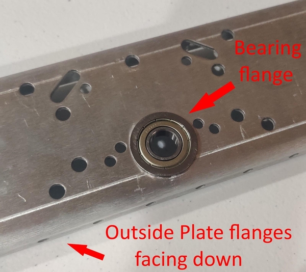
Two of the bearings used in the Toughbox have flanges while the other two do not. A flanged bearing has a small ring extending around it as shown below.
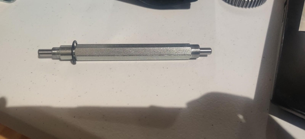
Press two R6ZZ 3/8” round inner diameter bearings (am-0516) without flanges into the two center holes of the Toughbox Mini S housing. Insert the Toughbox small 3/8” hex shaft (am-0152) into the bearing closer to the flat end of the gearbox housing.
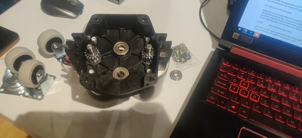
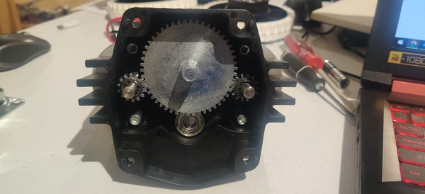
Take the 3/8” hex 50 tooth gear (am-4720) and place it onto the 3/8” hex shaft. Then add the 19 tooth gear onto the same shaft so it sits on top of the 50 tooth gear.
Install the 1/2” E-clip (am-0206) into the groove in the Toughbox 1/2” hex output shaft (am-4722) by pushing the shaft down onto the clip.
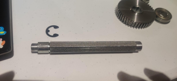
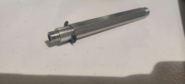
If you plan on adding encoders to the KitBot, install the encoder pin shafts (am-1323) into the 1/2” hex output shaft now. Clean the pins off and super glue them into the holes in the ends of each 1/2” hex output shaft. Let them dry before continuing.
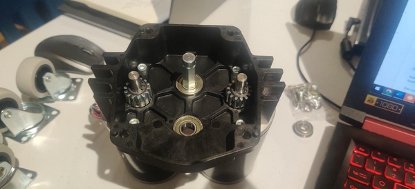
Insert the 1/2” hex output shaft into the other R6ZZ bearing with the E-clip closer to the bearing. Place the 45 tooth 1/2” hex gear (am-4712) onto the output shaft.
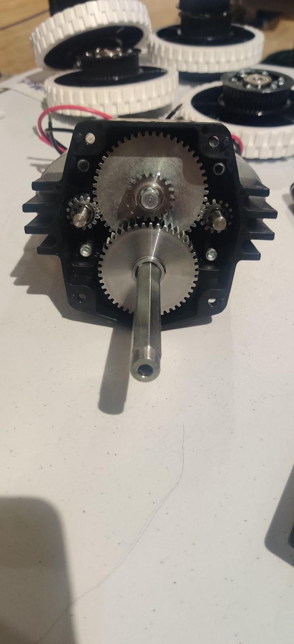
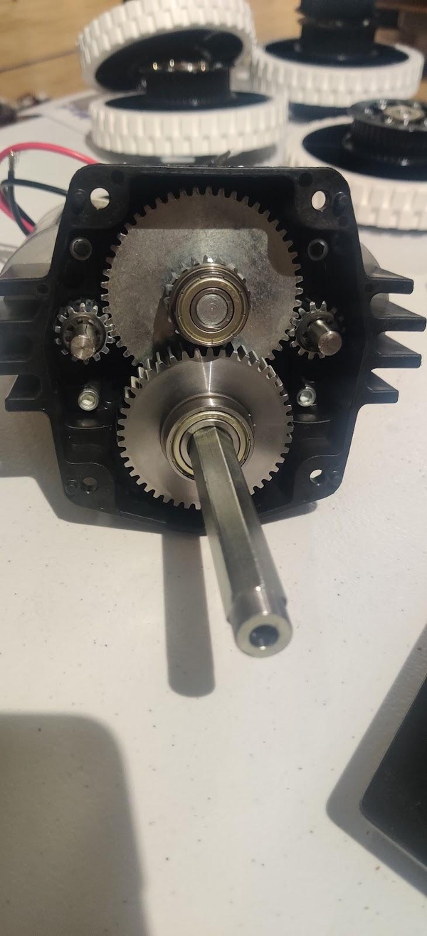
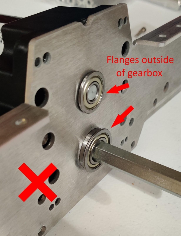
Place the FRZ6ZZ 3/8” round center bearing with flange (am-0028) onto the other end of the short 3/8” hex shaft on top of the 19 tooth gear, with the flange of the bearing closer to the gear. Place the FR8ZZ-HexHD 1/2” hex center bearing with flange on the 1/2” hex output shaft on top of the 45 tooth gear, with the flange of the bearing closer to the gear.
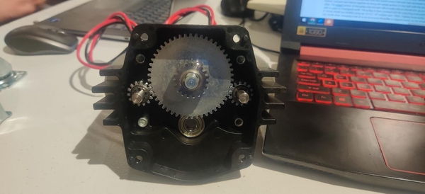
If your team has a convenient way to run your drivetrain motors now, such as an electronics test bed with motor controllers or other method of power delivery or by plugging the motors to a previous year’s robot, it is recommended that you run in the gearbox “dry” for thirty minutes at this point. Before greasing the gears inside, attach the Toughbox Mini S to the Chassis Inside Plate as described below and secure it. Connect whatever method you have for powering the motors and turn it on, leaving it to run in for thirty minutes. They may start out loud but should not produce an ear-splitting “squeal” or “screech.”
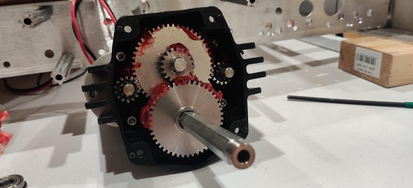
Once you have run in your gearbox, or if you do not have a convenient way to run in your gearboxes right now, apply red tacky grease (am-2768) to all the teeth of the gears. The flat surfaces of the gears are not as important as well-greasing the teeth where the gears actually mesh, and as the gearbox runs it will distribute the grease further.
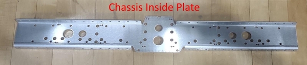
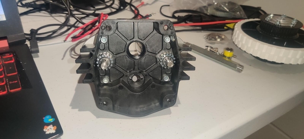
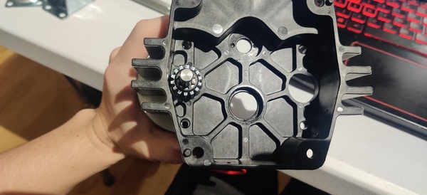
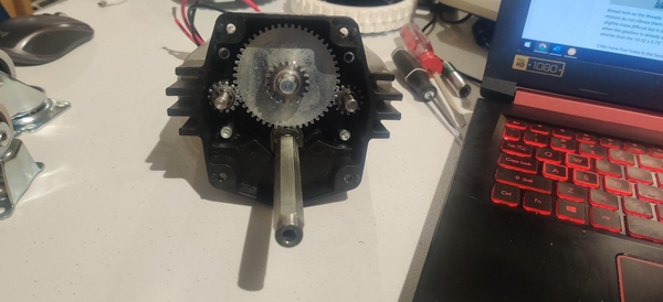
(Re)attach the Toughbox Mini S to the Chassis Inside Plate of the chassis using four 10-32 x 0.75” bolts (am-1047) and four 10-32 Nylock nuts (am-1042). The flat side of the gearbox lines up with the shorter side of the roughly trapezoidal gearbox mounting area in the center of the Chassis Inside Plates and the tapered side of the gearbox mates with the longer side of the trapezoid. The flanges on the Chassis Inside Plates should face away from the gearbox on the flat side (the top of the gearbox) and towards the gearbox on the tapered side (the bottom of the gearbox).
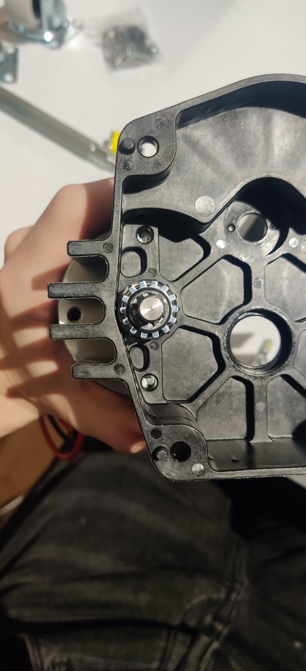
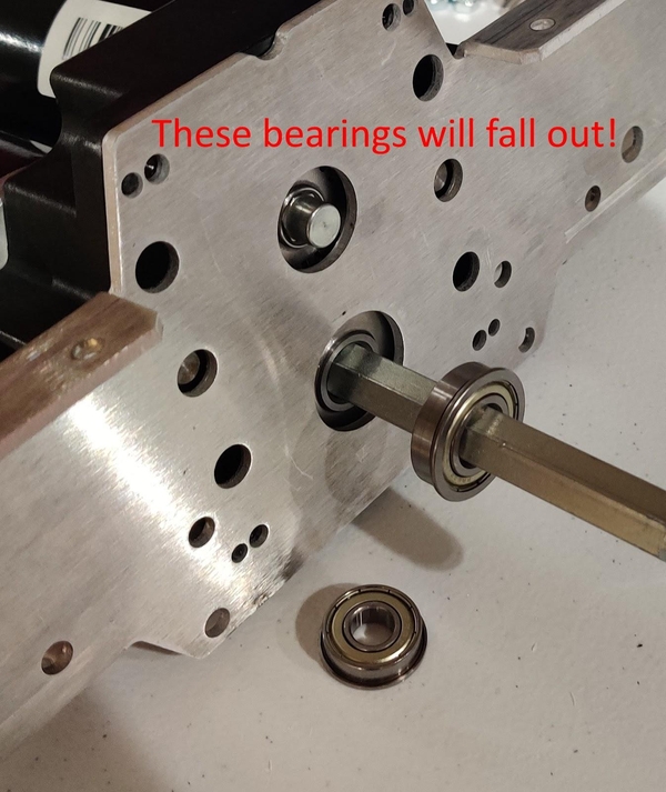
Make sure both of the flanged bearings are correctly “trapped” inside the gearbox by already being installed on the shafts when the gearbox is pushed into the Chassis Inside Plate - taking them out of the gearbox, inserting the gearbox’s shafts through the holes, and then sliding the bearings onto the shafts from the other side of the Chassis Inside Plate will leave the bearings able to fall out.
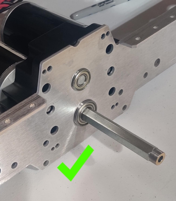
If the bearings do not want to fit in the chassis holes, they can be arbor pressed into place (be sure to get the flange on the correct side of the Chassis Inside Plate so that the flange will end up inside the gearbox!) or the holes can be enlarged slightly with a deburring tool.
The 10-32 x 0.75” bolts should be inserted into the Chassis Inside Plate and through the gearbox casing with the 10-32 Nylock nuts inserted into the hexagonal holes in the back of the gearbox casing.
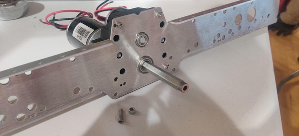
Complete these steps with both Toughboxes, affixing one to each Chassis Inside Plate.
Chassis Assembly
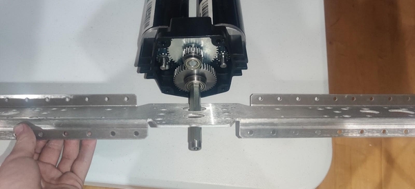
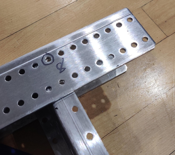
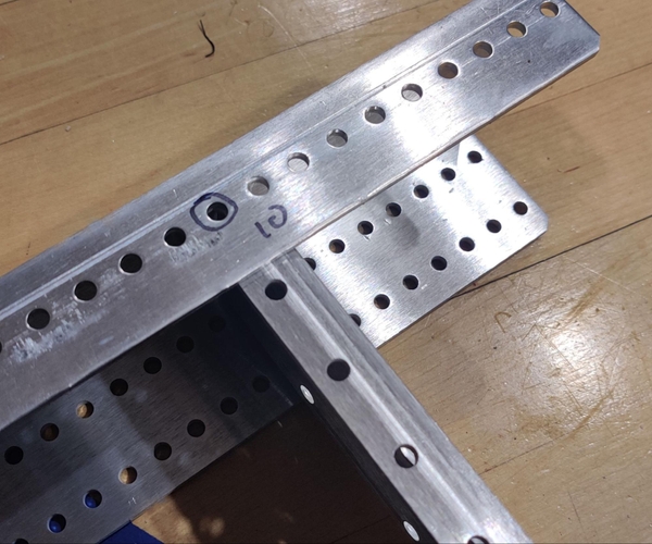
Insert one of the Chassis Inside Plates into one of the Chassis End Plates. The motors sticking out of the gearbox should face towards the middle of the robot with the output shaft sticking outwards. The top flange of the Chassis Inside Plates should point towards the outside of the robot while the bottom flange should face inwards. Line up the outermost hole in the upper flange of the Chassis Inside Plate with the 8th hole in from the edge of the top of the Chassis End Plate, with the first two holes in the bottom flange lining up with the 10th holes in from the edge of the bottom of the Chassis End Plate.
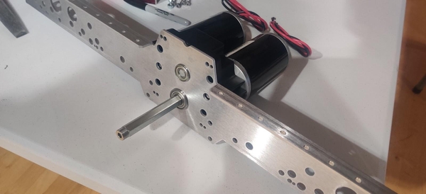
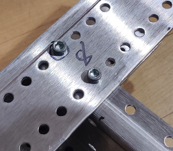
Attach the Inside and End plates with three 10-32 x 0.5” bolts (am-1002) and 10-32 Nylock nuts (am-1042) with two bolts through the longer top flange of the End Plate and the top flange of the Inside Plate and an additional bolt going through the bottom of the End Plate and the bottom flange of the Chassis Inside Plate. Mirror these steps with the other Chassis Inside Plate to attach the second side rail and gearbox to the Chassis End Plate.
The other End Plate is similarly attached to the Inner Side Plates with the holes in the top flanges lining up with the eighth holes from the edge of the top of the end plates.
If you can, prepare the electronics bellypan out of 0.5” thick plywood and slide it into place in the chassis now before the second end plate is installed.
Using a carpenter’s square or similar tool, check that the frame of the chassis is “square” - that is, check that all four of the corners of the chassis form 90 degree angles. If your chassis is “bent” or otherwise off-angle it will have problems driving correctly and it will be difficult to complete the rest of the robot. If necessary, loosen the bolts in the offending corners and shift the plates until they form right angles with each other.
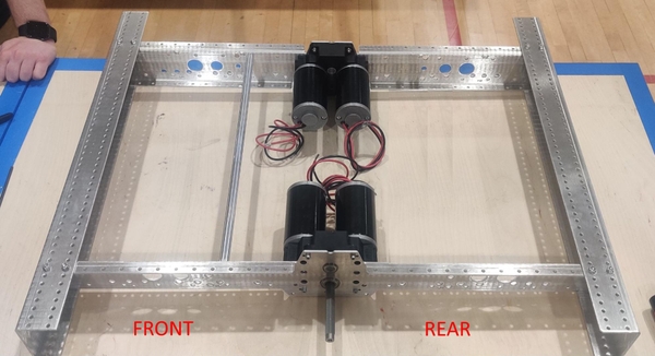
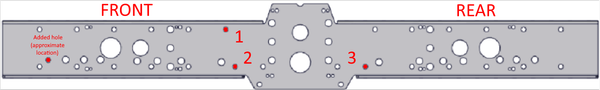
The churro in the front part of the chassis is installed in the AndyMark recommended location. If you plan on adding the Everybot additions to the KitBot, install the rear churro one churro hole further back.
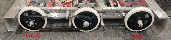
Your chassis will now have a front (the side with the churro closer to the middle) and a back (the other side of the robot with the churro closer to the Chassis End Plate). It is probably a good idea to label the chassis with front and back so your team can keep it straight when assembling the rest of the KitBot.
At this point, follow the FIRST KitBot plans to machine and assemble the launcher and frame, and attach it to the chassis, making sure the front of the mechanism is on the side with the churro closer to the center of the frame. After the hole attaching the front of the superstructure to the frame is added in step 4 of section 6.2.10 and the fitment of the mechanism is satisfactory the mechanism can be removed if desired.
Attach three of the 3.375” long churros to each side of the chassis using 1/4-20 x 0.75” form-threading bolts (am-1591 or am-1310) so that the churros extend outwards from the Chassis Inside Plate like the gearbox output shaft. Typically, four churros are installed on each side, but the angled portion of the KitBot mechanism mounts to one of these holes. Make sure that the installation of these churros is mirrored between the sides rather than rotated.
A 1/2” hex wrench can be used to hold churro in place while tightening the bolts with a 3/8” wrench or ratchet. These bolts will require additional force to cut the threads into the churros. If desired, the 3.375” churros can be pre-tapped for a 1/4-20 bolt on both ends.
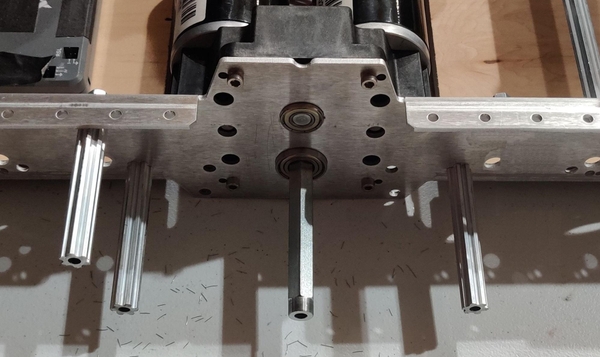
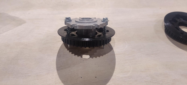
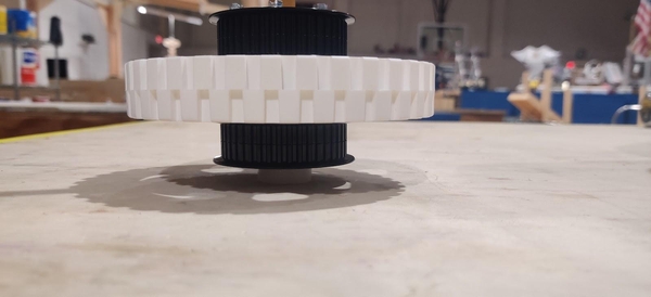
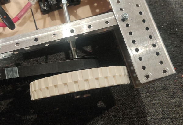
Place a center wheel with two pulleys on the Toughbox output shaft with the aluminum hex hub facing the gearbox. Place a nylon hex spacer (am-1305) onto the output shaft and press or tap it into the hole in the end of the pulley. The shaft will keep the spacer’s hexagonal bore aligned with the hex hub’s bore.
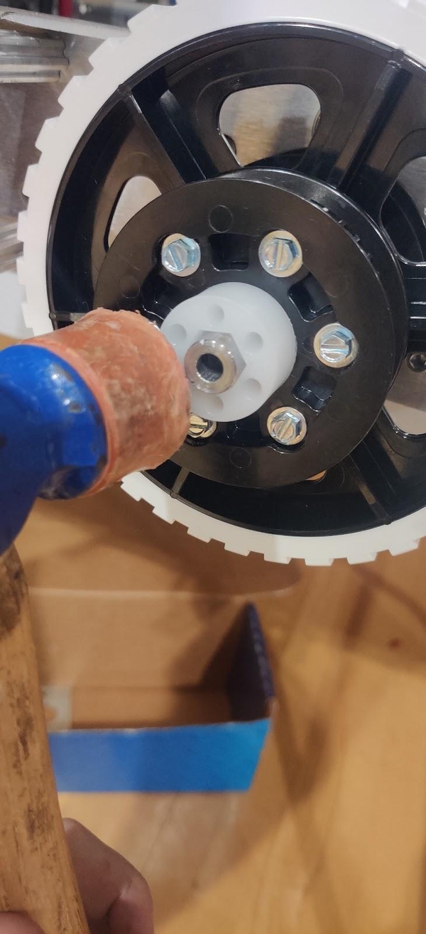
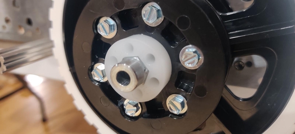
When the spacer is fully inserted into the wheel, the entire round portion at the end of the output shaft should be outside of the spacer.
If the spacer can not easily be pushed or tapped into place with a rubber mallet, you can remove the spacer and wheel and push the spacer into place by lining up the center hex patterns of the hub and spacer with a small piece of hex shaft or a churro and pushing the wheel down onto the spacer, similar to the way that the bearings were previously pushed into the front and rear wheels.
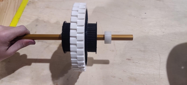
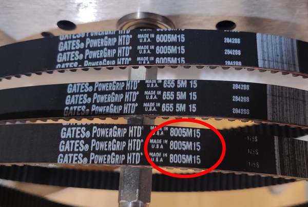
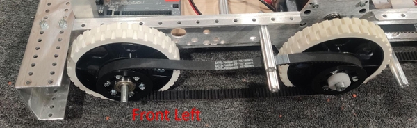
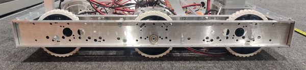
Loop two of the 160 tooth belts (am-2266, marked as 8005M15 on the belts themselves) around the center wheel. The belts will be stretched towards the front and back of the frame to couple the front and rear wheels to the driven inner wheel. The belt going towards the front of the chassis is looped around the lower churro and under the upper one, with the belt towards the rear looping around the single lower churro.
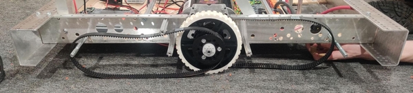
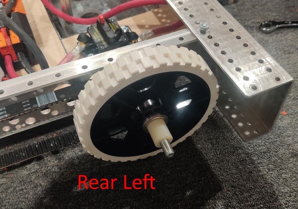
The photos in this section show the left side of the chassis with the front of the chassis to the left. The rear belts are to the inside of the chassis with the front belts closer to the outside of the frame. The orientation of the drive belts within the frame does not matter for the KitBot.
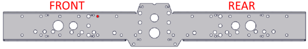
Insert one of the 3/8-16 4.25” bolts (am-1297) through the rear axle hole in the diagram above from the inside of the chassis so that it sticks out similar to the churros and gearbox output shaft. Slip a short 0.28” nylon spacer (am-1306) over the bolt.
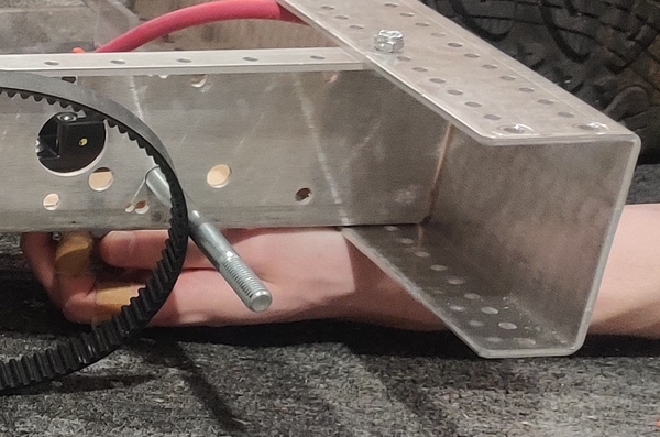
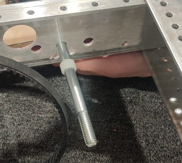
Take one of the four outer wheels and loop the belt around its pulley, making sure the pulley is towards the inside of the chassis and that the belt will run parallel with the side plates. Push the bolt through the two bearings in the wheel. You may find it is easier to pull the bolt slightly back into the chassis, line up the wheel on the end of the bolt, and then push the bolt all the way back through. Add a longer 0.85” nylon spacer (am-1307) onto the end of the bolt.
A 3/8-16 nut can be finger-tightened to the end of the axle to hold this assembly in place while setting up the other wheel on this side if desired.
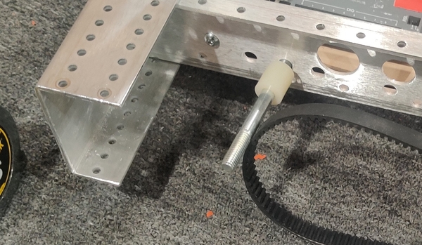
Insert another 3/8-16 4.25” bolt (am-1297) through the front axle hole in the diagram above from the inside of the chassis so that it sticks out similar to the churros and gearbox output shaft. This time, put a longer 0.85” nylon spacer onto the end of the bolt first.
Pull the other 160 tooth belt towards the front of the robot, making sure it fits over the middle wheel’s outer pulley. Take another wheel and put the belt around its pulley, making sure the pulley is toward the outside of the chassis this time so that it is similarly parallel with the Chassis Inside Plate when the bolt is pushed through the wheel’s bearings.
Now slip a short 0.28” nylon spacer over the end of the bolt. A nut can be tightened by hand to hold the stackup in place if necessary. With the churros, belts, wheels, and axles all in the correct position, the Chassis Outside Plate can be added.
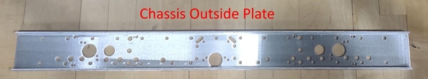
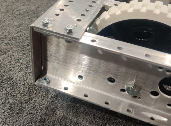
Press a FR8ZZ 1/2“ round bearing (am-0030) into the center hole of each Chassis Outside Plate, being sure to press it in from the opposite side of the Outside Plate’s flanges so that the bearing will be trapped in place correctly. Remove any nuts from the end of the front and rear axles and make sure that none of the spacers fall off the ends.
With the Outside Plate’s flanges pointing out, line the bearing up with the Toughbox output hex shaft and hold the front and rear wheels in place so the axle bolts line up with the matching holes in the Outside Plate. Push the Chassis Outside Plates into the front and back chassis end plates so that the holes in the Outside Plate’s flanges line up with the outermost holes in the Chassis End Plates.
Secure the Chassis Outside Plates in place using six 10-32 x 0.5” bolts and 10-32 Nylock nuts each. Secure the front and rear axles by tightening the 3/8-16 nuts onto the axle bolts so that the wheels can still spin. The axle bolts and nuts are both tightened using a 9/16” socket or wrench. Attach the four 3.375” churros to the Chassis Outside Plate using 1/4-20 x 0.75” form-threading bolts (am-1591 or am-1310).
The same steps are followed on the other side of the chassis to complete the drivetrain. Both sides can be assembled simultaneously as long as your team has enough space, tools, and people.