Chassis Assembly
Insert one of the Chassis Inside Plates into one of the Chassis End Plates. The motors sticking out of the gearbox should face towards the middle of the robot with the output shaft sticking outwards. The top flange of the Chassis Inside Plates should point towards the outside of the robot while the bottom flange should face inwards. Line up the outermost hole in the upper flange of the Chassis Inside Plate with the 8th hole in from the edge of the top of the Chassis End Plate, with the first two holes in the bottom flange lining up with the 10th holes in from the edge of the bottom of the Chassis End Plate.
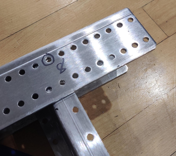
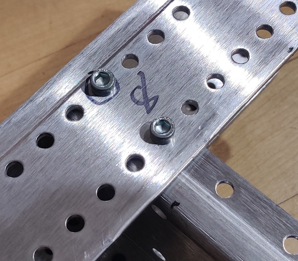
Attach the Inside and End plates with three 10-32 x 0.5” bolts (am-1002) and 10-32 Nylock nuts (am-1042) with two bolts through the longer top flange of the End Plate and the top flange of the Inside Plate and an additional bolt going through the bottom of the End Plate and the bottom flange of the Chassis Inside Plate. Mirror these steps with the other Chassis Inside Plate to attach the second side rail and gearbox to the Chassis End Plate.
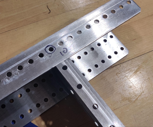
The other End Plate is similarly attached to the Inner Side Plates with the holes in the top flanges lining up with the eighth holes from the edge of the top of the end plates.
If you can, prepare the electronics bellypan out of 0.5” thick plywood and slide it into place in the chassis now before the second end plate is installed.
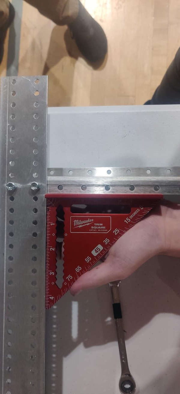
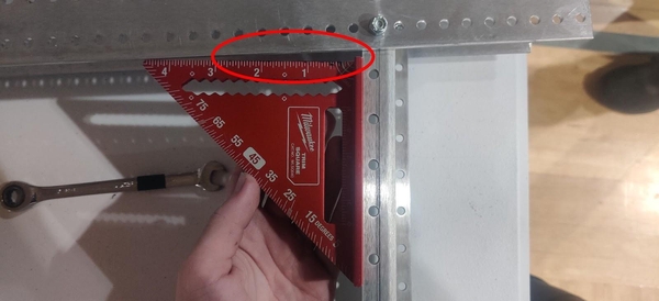
Using a carpenter’s square or similar tool, check that the frame of the chassis is “square” - that is, check that all four of the corners of the chassis form 90 degree angles. If your chassis is “bent” or otherwise off-angle it will have problems driving correctly and it will be difficult to complete the rest of the robot. If necessary, loosen the bolts in the offending corners and shift the plates until they form right angles with each other.
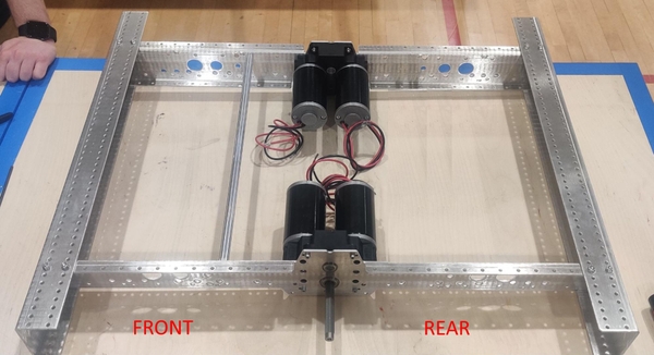
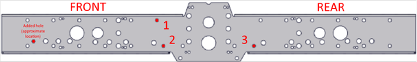
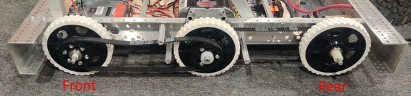
The churro in the front part of the chassis is installed in the AndyMark recommended location. If you plan on adding the Everybot additions to the KitBot, install the rear churro one churro hole further back.
Your chassis will now have a front (the side with the churro closer to the middle) and a back (the other side of the robot with the churro closer to the Chassis End Plate). It is probably a good idea to label the chassis with front and back so your team can keep it straight when assembling the rest of the KitBot.
At this point, follow the FIRST KitBot plans to machine and assemble the launcher and frame, and attach it to the chassis, making sure the front of the mechanism is on the side with the churro closer to the center of the frame. After the hole attaching the front of the superstructure to the frame is added in step 4 of section 6.2.10 and the fitment of the mechanism is satisfactory the mechanism can be removed if desired.
Attach three of the 3.375” long churros to each side of the chassis using 1/4-20 x 0.75” form-threading bolts (am-1591 or am-1310) so that the churros extend outwards from the Chassis Inside Plate like the gearbox output shaft. Typically, four churros are installed on each side, but the angled portion of the KitBot mechanism mounts to one of these holes. Make sure that the installation of these churros is mirrored between the sides rather than rotated.
A 1/2” hex wrench can be used to hold churro in place while tightening the bolts with a 3/8” wrench or ratchet. These bolts will require additional force to cut the threads into the churros. If desired, the 3.375” churros can be pre-tapped for a 1/4-20 bolt on both ends.
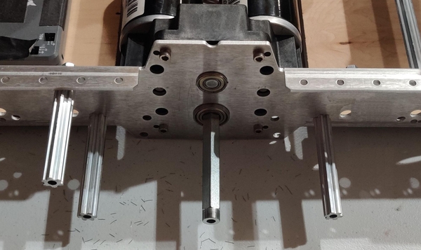
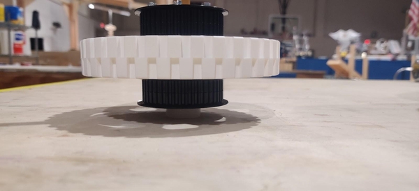
Place a center wheel with two pulleys on the Toughbox output shaft with the aluminum hex hub facing the gearbox. Place a nylon hex spacer (am-1305) onto the output shaft and press or tap it into the hole in the end of the pulley. The shaft will keep the spacer’s hexagonal bore aligned with the hex hub’s bore.
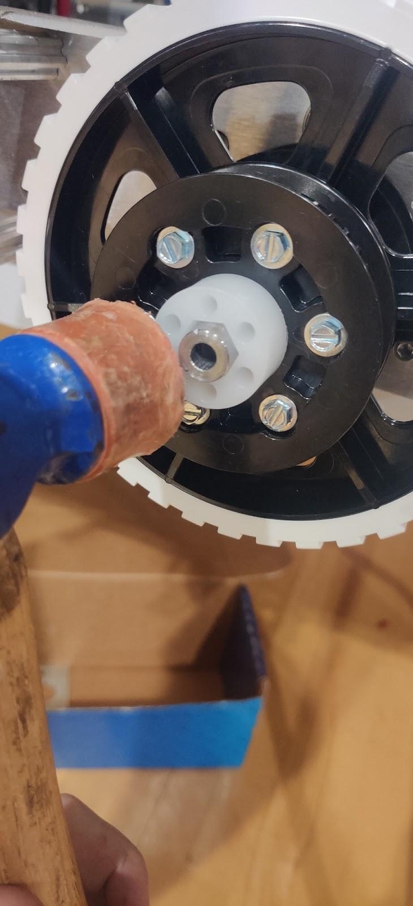
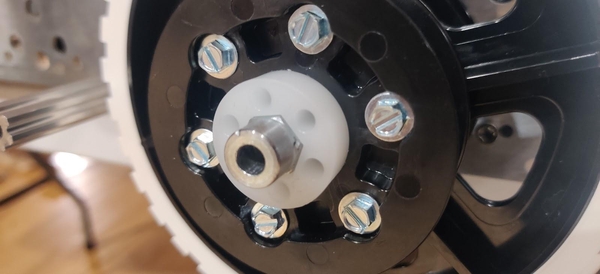
When the spacer is fully inserted into the wheel, the entire round portion at the end of the output shaft should be outside of the spacer.
If the spacer can not easily be pushed or tapped into place with a rubber mallet, you can remove the spacer and wheel and push the spacer into place by lining up the center hex patterns of the hub and spacer with a small piece of hex shaft or a churro and pushing the wheel down onto the spacer, similar to the way that the bearings were previously pushed into the front and rear wheels.
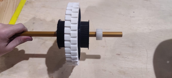
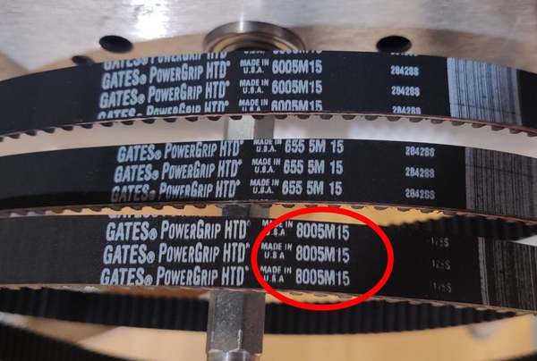
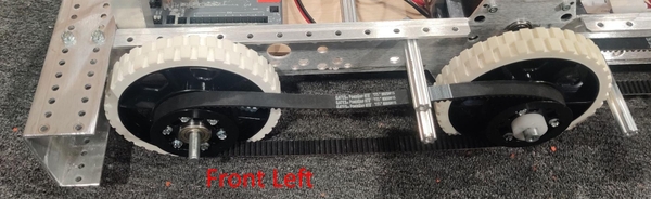
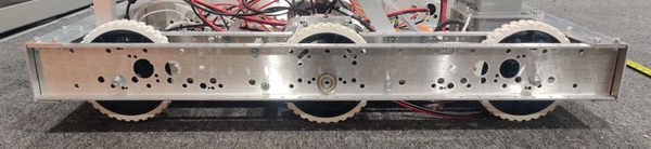
Loop two of the 160 tooth belts (am-2266, marked as 8005M15 on the belts themselves) around the center wheel. The belts will be stretched towards the front and back of the frame to couple the front and rear wheels to the driven inner wheel. The belt going towards the front of the chassis is looped around the lower churro and under the upper one, with the belt towards the rear looping around the single lower churro.
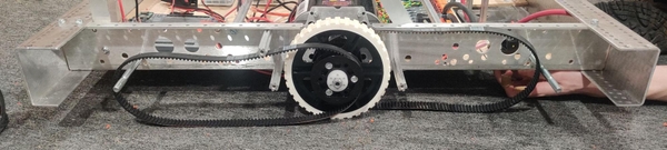
The photos in this section show the left side of the chassis with the front of the chassis to the left. The rear belts are to the inside of the chassis with the front belts closer to the outside of the frame. The orientation of the drive belts within the frame does not matter for the KitBot.
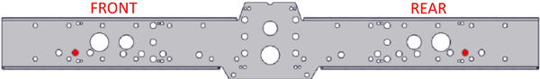
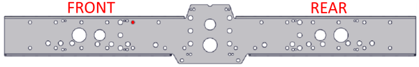
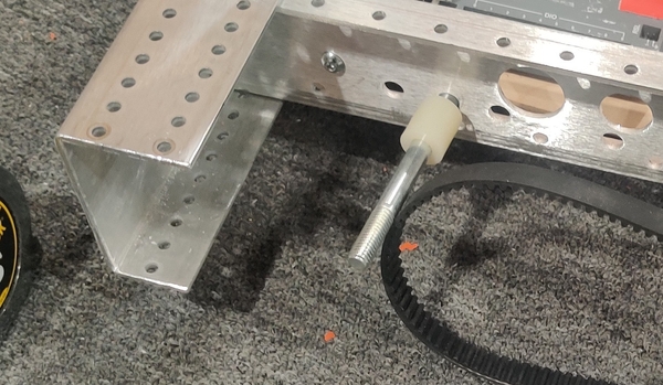
Insert one of the 3/8-16 4.25” bolts (am-1297) through the rear axle hole in the diagram above from the inside of the chassis so that it sticks out similar to the churros and gearbox output shaft. Slip a short 0.28” nylon spacer (am-1306) over the bolt.
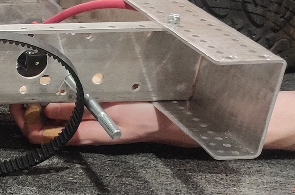
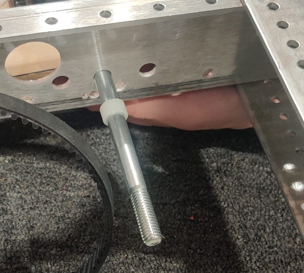
Take one of the four outer wheels and loop the belt around its pulley, making sure the pulley is towards the inside of the chassis and that the belt will run parallel with the side plates. Push the bolt through the two bearings in the wheel. You may find it is easier to pull the bolt slightly back into the chassis, line up the wheel on the end of the bolt, and then push the bolt all the way back through. Add a longer 0.85” nylon spacer (am-1307) onto the end of the bolt.
A 3/8-16 nut can be finger-tightened to the end of the axle to hold this assembly in place while setting up the other wheel on this side if desired.
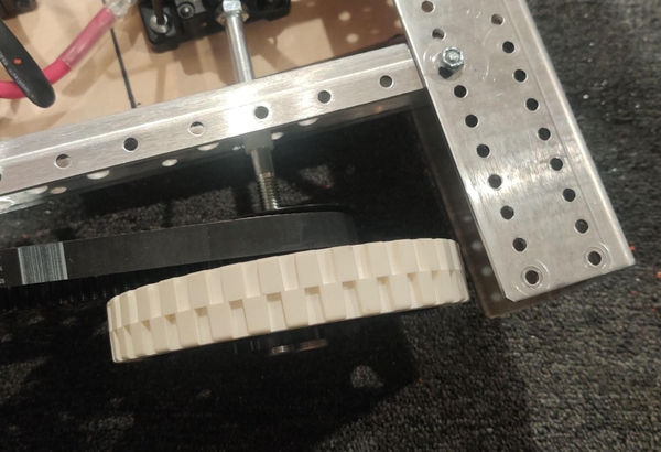
Insert another 3/8-16 4.25” bolt (am-1297) through the front axle hole in the diagram above from the inside of the chassis so that it sticks out similar to the churros and gearbox output shaft. This time, put a longer 0.85” nylon spacer onto the end of the bolt first.
Pull the other 160 tooth belt towards the front of the robot, making sure it fits over the middle wheel’s outer pulley. Take another wheel and put the belt around its pulley, making sure the pulley is toward the outside of the chassis this time so that it is similarly parallel with the Chassis Inside Plate when the bolt is pushed through the wheel’s bearings.
Now slip a short 0.28” nylon spacer over the end of the bolt. A nut can be tightened by hand to hold the stackup in place if necessary. With the churros, belts, wheels, and axles all in the correct position, the Chassis Outside Plate can be added.
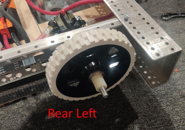
Press a FR8ZZ 1/2“ round bearing (am-0030) into the center hole of each Chassis Outside Plate, being sure to press it in from the opposite side of the Outside Plate’s flanges so that the bearing will be trapped in place correctly. Remove any nuts from the end of the front and rear axles and make sure that none of the spacers fall off the ends.
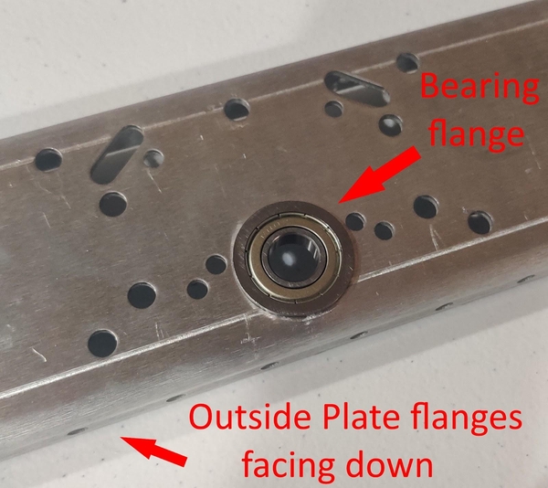
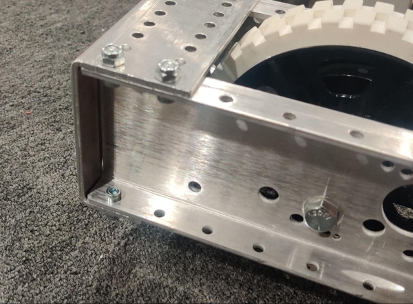
With the Outside Plate’s flanges pointing out, line the bearing up with the Toughbox output hex shaft and hold the front and rear wheels in place so the axle bolts line up with the matching holes in the Outside Plate. Push the Chassis Outside Plates into the front and back chassis end plates so that the holes in the Outside Plate’s flanges line up with the outermost holes in the Chassis End Plates.
Secure the Chassis Outside Plates in place using six 10-32 x 0.5” bolts and 10-32 Nylock nuts each. Secure the front and rear axles by tightening the 3/8-16 nuts onto the axle bolts so that the wheels can still spin. The axle bolts and nuts are both tightened using a 9/16” socket or wrench. Attach the four 3.375” churros to the Chassis Outside Plate using 1/4-20 x 0.75” form-threading bolts (am-1591 or am-1310).
The same steps are followed on the other side of the chassis to complete the drivetrain. Both sides can be assembled simultaneously as long as your team has enough space, tools, and people.