KitBot Electrical
The KitBot electrical system can be wired using wire and connectors included in the Kit of Parts, with the electrical components coming in the Rookie Kit of Parts or retained from previous seasons for non-rookies. The electrical system can be wired using whatever legal combination of newer REV and older CTRE control system components your team has. Rookie teams receive a full system of the newer REV control system components which this guide will primarily focus on because it is assumed that teams with older control systems have some experience with FRC wiring.
How to Wire a Robot video from FIRST
For more visual aid we highly recommend watching this video. Wiring a battery, main breaker, motor controllers, the roboRIO, RSL (Robot Signal Light) and CAN bus is covered.
Introduction to FRC Robot Wiring
A that FIRST linked that we also want to echo. Here are two large pieces of information when using this resource:
-
Use CAN over PWM, we have had issues with SPARK MAXs in PWM mode and found CAN to be significantly more reliable
-
We heavily recommend using inline WAGO connectors over the quick disconnect crimps included in the Kit of Parts as they are easier to implement and require less training and no crimping.
If you plan on using the quick disconnects included in the kit, please see our video below
Quick Disconnect Crimping Video
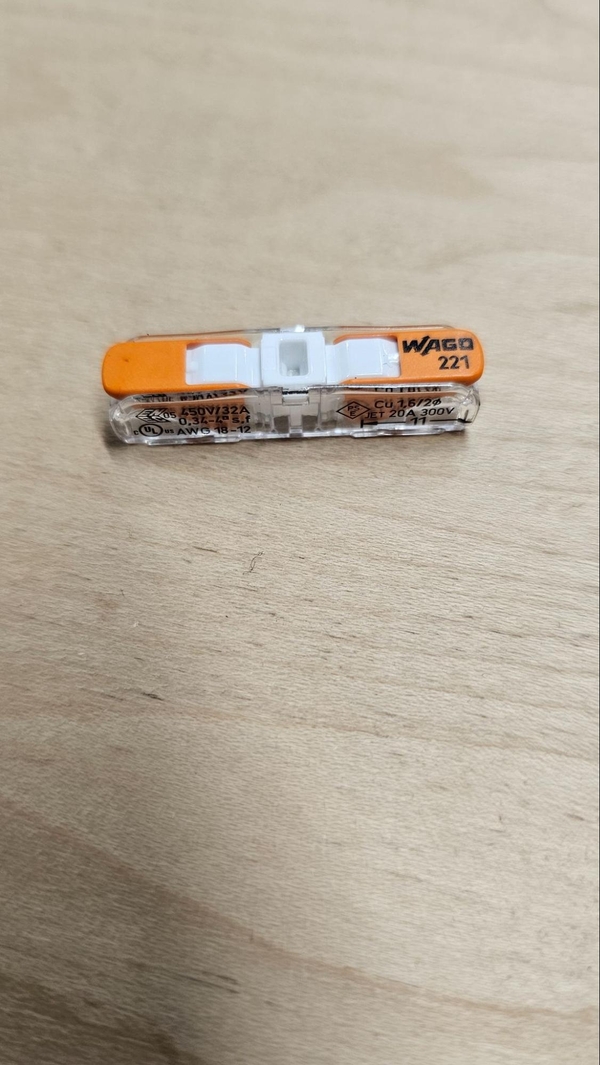
WAGO (requires no crimping) Quick disconnect (requires crimping)
For more tips on navigating this resource please the Everybot Evergreens electrical section.
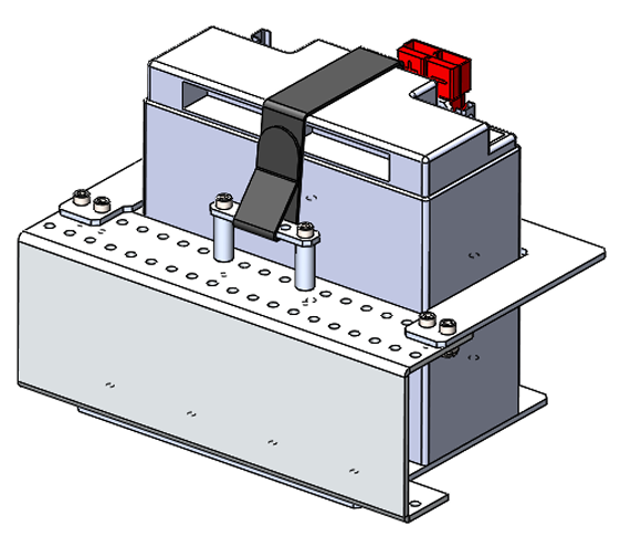
Battery Bracket
The battery bracket is included with the AndyMark Kit of Parts Chassis that you most likely received in your kickoff kit on kickoff. We will include instructions for assembling the battery bracket but the official AndyMark instructions can be found in the linked text. Some of the images and text in the following section come from the AndyMark manual.
“Place two 3.375” Churros (am-2569) between the Bottom Plate (am-3959) and the C Plate (am3958). Secure the Churros to the plate with four 1/4-20 x 0.750” Thread Forming Screws (am-1310). Make sure the tabs on both plates are pointing upwards.“ - AM instruction
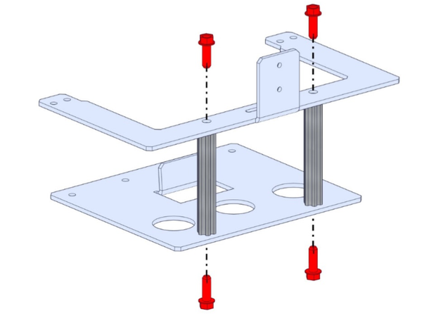
The bracket is installed slightly off center in the back of the robot (the opposite side from the scoring mechanism). Looking at the rear Chassis End Plate from behind the robot, the leftmost hole in the top plate of the AndyMark Battery Bracket should be located in the 18th hole along the Chassis End Plate top flange when counting from the left edge to the right. This will be 8.75” away from the left side of the chassis when viewed from the back. Make sure the top plate is on top of the Chassis End Plate upper flange and the lower plate is below the Chassis End Plate lower flange.
Use four 0.5” 10-32 socket head bolts to secure the top plate to the chassis. The socket head should be pointed up, with the nylock nuts on bottom. The bolts use a 5/32” allen key and the nuts require a 3/8” wrench, ideally a ratcheting one.
Use four 0.5” 10-32 socket heads to secure the bottom plate to the chassis, this time with the bolt head facing the floor.
Next install the battery clamp, which is the strip with 5 holes, on top of the cylindrical spacers with the 1.5” 10-32 bolts with nylock nuts underneath. There should be five open holes from the plate to one side of the top battery plate to the location of the battery clamp.
“Feed the battery strap through the top of the slot, loop around and through the buckle. This strap can be left permanently attached to this bracket.” - AM instruction
Bellypan
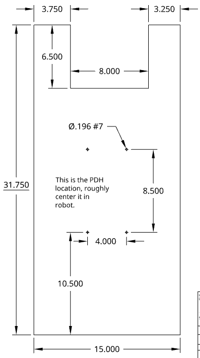
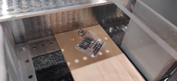
The KitBot shopping list includes a sheet of 1/2 inch thick plywood intended to be cut down to form the bellypan and electronics board of the robot. The plywood sheet should be cut down to 15” by 31.75” to fit within the chassis with an 8” wide and 6.5” deep cutout located 3.75” from one side and 3.25” from the other to fit around the battery bracket.

The easiest way to install the bellypan is to slide it in from the front or rear of the chassis with the front or rear end plate removed. If you have referenced the KitBot CAD, the churros across the inside of the chassis may be positioned too low and interfere with the bellypan. Move the churros up to the AndyMark recommended holes if needed.
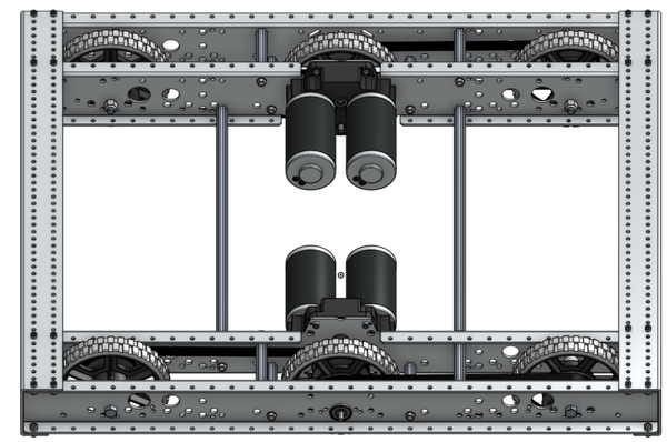
The bellypan sits under the motors and churros and between the portions of the Toughbox Mini gearboxes that extend downwards. A more spacious bellypan could be made that fills the gaps to the sides in the front and rear of the chassis with cutouts where the gearboxes hang lower, but this is not necessary to fit the required electrical components of the KitBot.
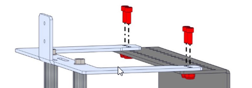
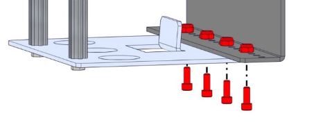
The bellypan should be bolted down to the Chassis End Rails to keep it from shifting around inside the robot. We used four 10-32 x 0.75” bolts towards each of the four corners of the plywood bellypan. The easiest way to do this is to turn the robot on its side and use a #7 drill bit to match drill through a hole in the Chassis End Plate bottom flange where there are no electrical components. Have someone else hold the bellypan down in the frame so that the drill goes directly into the wood instead of pushing the bellypan up into the chassis, being sure to keep their hands away from where the drill bit will come through the wood. Install the bolts one at a time after drilling the holes to ensure all four holes will end up lining up. Insert them from the bottom so just the head of the bolt hangs down below the frame.
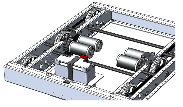
Component Layout
The component layout shown and described here is merely one potential layout and your team can choose to lay out your electrical system in any sensible way you want. If you plan on adapting your KitBot into an Everybot the layout described here should be easily adapted to account for the changes between the two designs.
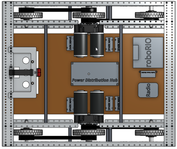
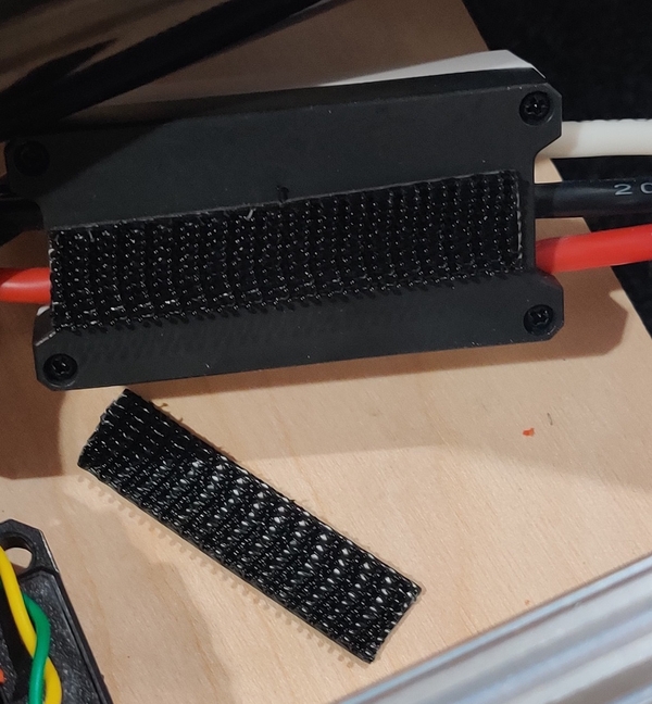
We attached our components using a mix of zip ties through hand-drilled holes in the 1/2” plywood and stickyback dual lock (included in the Kit of Parts) for ease of installation and component removal if necessary. A more secure mounting system may be desirable for a competition robot that will see heavy use and collisions. Zip ties around or through mounting features of components are a good option.
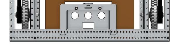
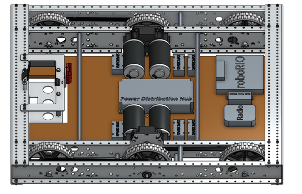
The front of the bellypan contains the roboRIO, radio, and power delivery for the radio (either the Radio Power Module or Voltage Regulator Module). These components had strips of dual lock applied with mating strips on the wood bellypan. The adhesive on the rear of the dual lock may not grip the plywood surface over time, and zip ties or bolts (or a polycarbonate bellypan) would probably hold up better during competition.
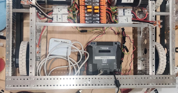
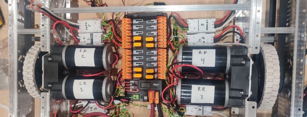
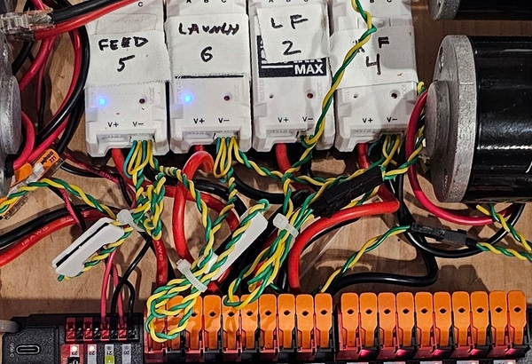
The middle of the bellypan holds the Power Distribution Hub (PDH). The PDH is held down with dual lock to make it easy to lift up to insert and remove wires for the motor controllers. The six motor controllers sit on either side of the drivetrain motors. The two rear drivetrain motor controllers sit behind the motors while the two front drivetrain motor controllers and the feeder and launcher motor controllers are in front of the drivetrain motors. Two more Spark Max motor controllers will be added if your team plans on adding the Everybot additions to the KitBot, one in the rear and one in the front.
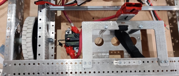
The main breaker is located to the left of the battery bracket and was zip-tied down, but bolts are generally preferred.
Power Wiring
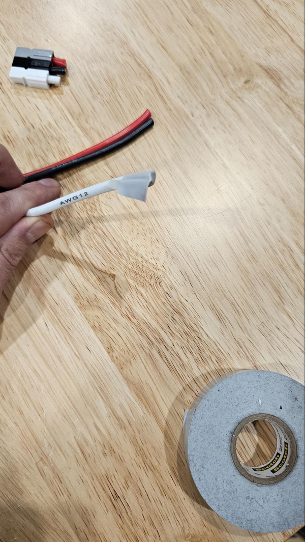
Thick 6 gauge wire (provided in the Kit of Parts) is used to connect the battery connector to the main breaker and Power Distribution Hub or Panel. Take one of the provided battery cables with a large plastic Anderson connector on one end and crimp a ring terminal to just the red wire if using a newer REV Power Distribution Hub (PDH) or both the red and black wires if using the older Power Distribution Panel (PDP). Eight 6AWG ring terminals are included in the Rookie Kit of Parts that can be used for this. Make sure the crimp is secure by pulling on it after crimping, if these connections are loose they can and will cause your robot to lose power as they are knocked around in matches.
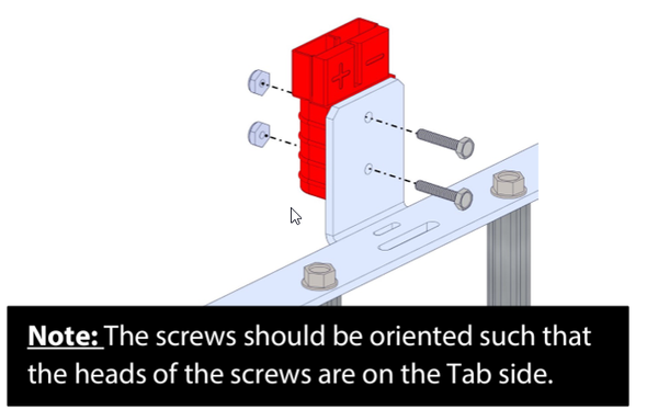
The Anderson Connector can be screwed into the tab on the battery bracket using the provided nuts and bolts and the black wire can be connected to the negative terminal on the power distribution board using either the WAGO lever or the bolt post depending on which version you are using. The red wire on the battery connector should then be attached to the “BATT” side of the main breaker (this is not strictly necessary, either the BATT or AUX terminal will work).
“Secure the Robot Side SB-Series Battery Connector to the tab on the C Plate using two #6-32 x 0.750” Hex Head Screws (am-1424) and #6-32 Nylock Jam Nuts (am-1419). The wires from this connector should go to your main robot breaker and power distribution panel.“ - AM instruction
Cut a section of the red 6 gauge wire provided in the kit down to an appropriate length and crimp a ring terminal on one end if using the PDH or both ends if using the PDP. Bolt the ring terminal to the AUX side of the main breaker and attach the other side to the positive terminal of the PDH/PDP. Cover any exposed metal on the main breaker connectors with electrical tape.
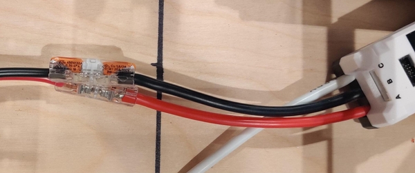
The six Spark Maxes should be able to be plugged directly into the PDP/PDH by stripping the red and black wires on the power input side of the motor controllers (the side with only the red and black wire coming out, not the side with red, black, and white wires) and inserting the wire into the PDP/PDH in adjacent red and black ports, inserting the red wire into the red receptacle and the black into the black. The slot used does not matter as long as you remember to place breakers into the slots that are used. If necessary, use 12 gauge wire to make extensions to connect the power input wires to the PDH/PDP outputs, with a WAGO connector or other quick disconnect connecting the controller to the extension wire.
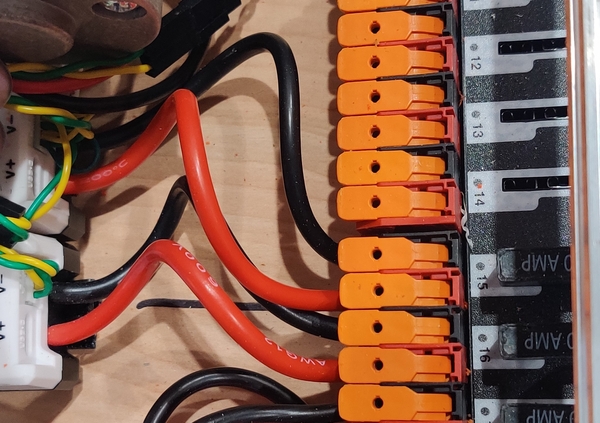
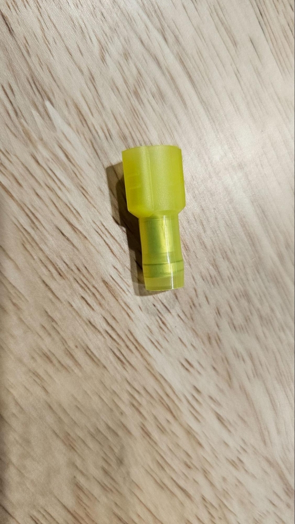
The motors are plugged into their motor controllers by stripping the ends of the red and black motor wires (if necessary) as well as just the red and black wires coming out of the motor output side of the Spark Maxes. Connect the red to red and black to black using WAGOs or another quick disconnect.
Do not worry about the white wire if using the provided CIM motors for the KitBot. Wrap some electrical tape around the white wire if it is unused to prevent the wire inside from contacting metal components of the robot. It does need to be connected (along with the hall effect sensor cable) if using NEO motors. In our testing we preferred CIMs over NEOs in all locations.
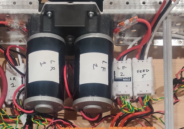
When the motors are plugged in to their controllers, it is probably a good idea to label the motors and controllers with what they are as well as their ID numbers. The numbering for both the default PWM control code and our adapted CAN control code are as follows:
1 - Left rear drive motor
2 - Left front drive motor
3 - Right rear drive motor
4 - Right front drive motor
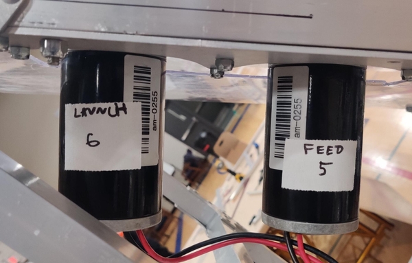
5 - Feed motor (lower of two mechanism motors)
6 - Launch motor (higher of two mechanism motors)
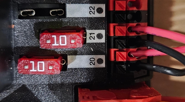
Two pairs of 18 gauge wire run from the PDH auxiliary power slots to the roboRIO power connector and the Radio Power Module or Voltage Regulator Module power inputs. On the PDH the slots numbered 20 to 22 near the battery voltage indicator can be used for the roboRIO or radio power, just install 10 amp fuses in the slots used. The positive red wire screws into the “V” (for voltage) connector of the roboRIO’s power terminal and the negative black wire goes to the “C” (for common) connector.
When using the Radio Power Module, the Ethernet cables (covered in the Data section) connecting the roboRIO to the radio through the module will provide the radio with power. If you are using the Voltage Regulator Module, a passive Power Over Ethernet (POE) injector like the orange REV cable included in the kit of parts is recommended. The POE cable should have the red and black wires with ferrules preinstalled inserted into the 12V/2A terminals on the VRM, with the optional barrel jack plugged into the other pair of 12V/2A connectors if desired.
Data Wiring
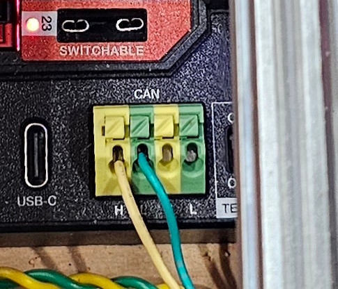
We suggest using the CAN bus over PWM cables to control the motor controllers as the wiring is neater and there are sometimes issues with using PWM control with Spark Max controllers. The CAN network or “bus” consists of a daisy-chain connecting every component on the bus. The CAN bus begins at the CAN ports located near the power connector on the roboRIO and terminates at the CAN connectors on the PDP or PDH, passing through each of the Spark Max motor controllers on the way.
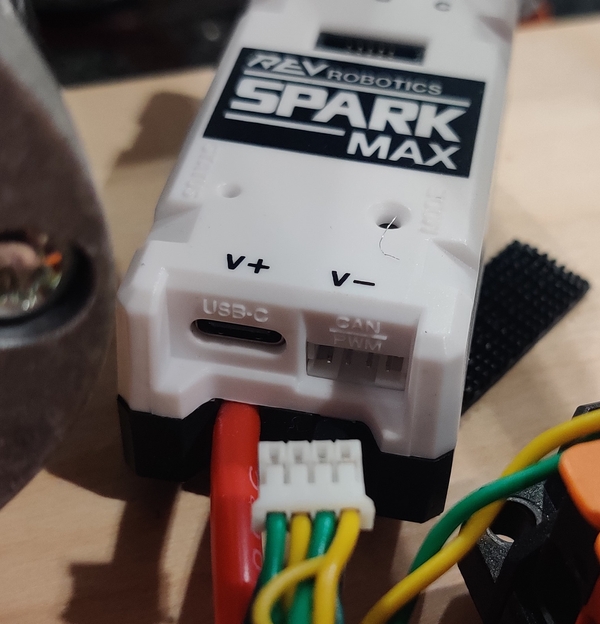
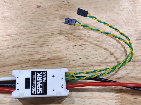
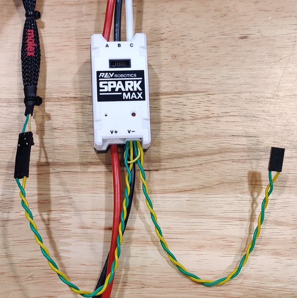
The Spark Maxes come with two data cables, a black and white PWM cable and a CAN cable with two pairs of yellow and green wires which plug into the keyed white connector next to the USB C port on the power input side of the controller. The side of the connector with the small tab faces down when inserting it into the port.
One of the pairs of yellow and green wire will connect to the previous device in the chain and the other will connect to the next, with the order things are plugged in being irrelevant to the function of the bus.
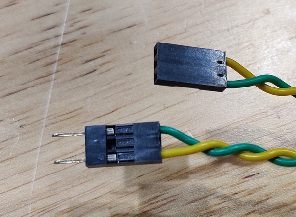
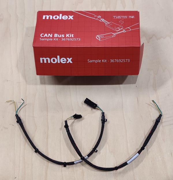
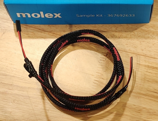
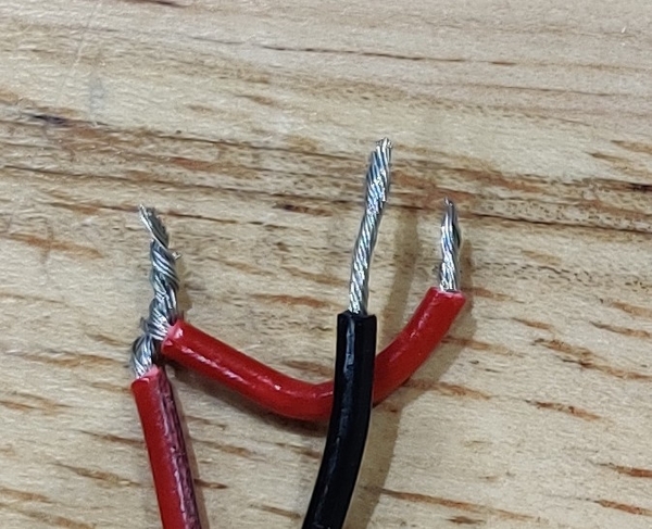
The Spark Max CAN cables come with servo-style pin header connectors. One connector has the protruding pins while the other has the mating receptacle. There is a CAN connection kit provided by Molex in the black Kit of Parts tote that has some cables that can be used to connect these servo-style pin headers to the terminals on the roboRIO and PDP/PDH as they expect a bare wire connection. Take one of these wires and remove the pre-cut section of insulation on the end that does not have a servo connector. Insert the yellow wire into the H (YEL) connector on the roboRIO and the green wire into the L (GRN) port. The other end of the cable can then be plugged into one of the motor controller connectors of the opposite type.
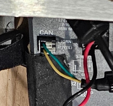
The other connector on that same motor controller can then be plugged into the opposite type on the next controller and so on until the CAN chain has passed through every motor controller, leaving one controller on the “end” of the chain with a free connector. Match the colors of the wires at every connection (yellow to yellow and green to green).
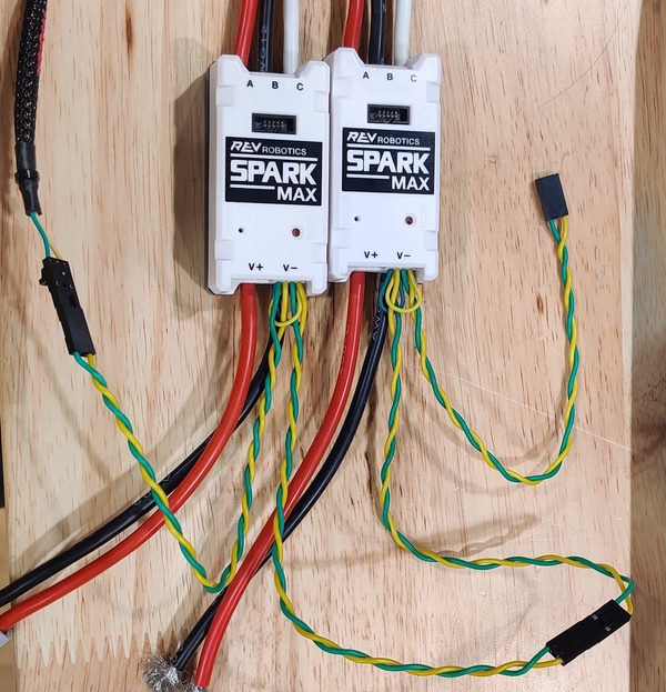
The white clips provided with the Spark Maxes can be used to hold the servo connectors together, and excess wire can be bundled together with zip ties. Take a Molex CAN cable with the opposite connector to the free Spark Max cable end and plug it into the Spark Max. The Molex connectors have tabs for a locking system which the REV cables do not have, meaning the white clips will not fit over the connection, so a strip of electrical tape or other method of holding the two connectors together so they can not be shaken loose during competition is a good idea. Remove the precut section of insulation from the other side of the Molex wire and plug the wires into either the left or right pair of connectors on the PDP/PDH’s CAN terminals, making sure the terminating resistor (labeled TERM) is turned on to complete the CAN chain.
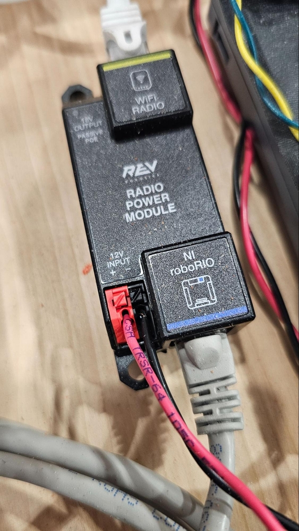
The radio needs to be plugged into the Ethernet jack on the roboRIO. If the Radio Power Module (RPM) is being used, run one Ethernet cable from the roboRIO’s port to the roboRIO side of the RPM and a second cable from the Radio side of the RPM to the port on the radio closer to the barrel jack.
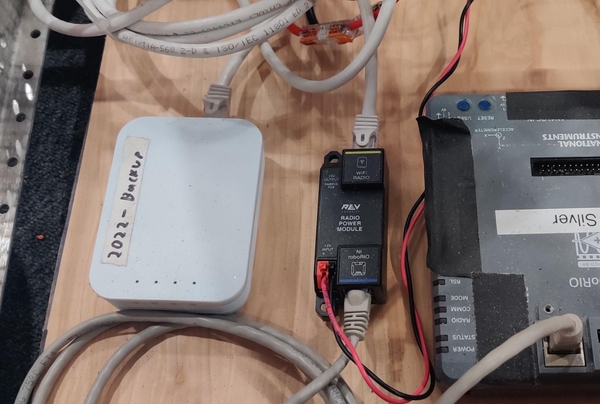
If the VRM is being used with a Power Over Ethernet cable, plug the Ethernet cable end into the radio port closer to the barrel jack and plug an Ethernet cable between the Ethernet jack on the other end of the POE cable and the Ethernet jack on the roboRIO.
The Ethernet jack closer to the barrel connector is the only port that can accept the 12 volt POE power the robot provides, and plugging into the outer port with either the VRM or RPM will not actually power the radio.
Miscellaneous
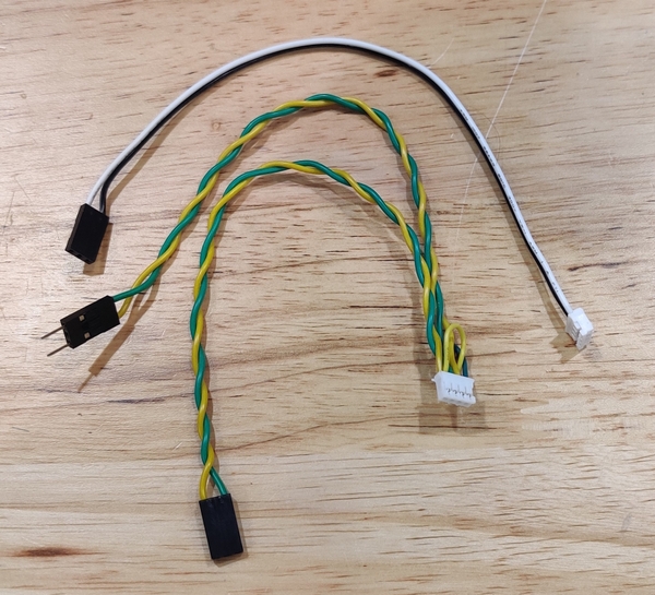
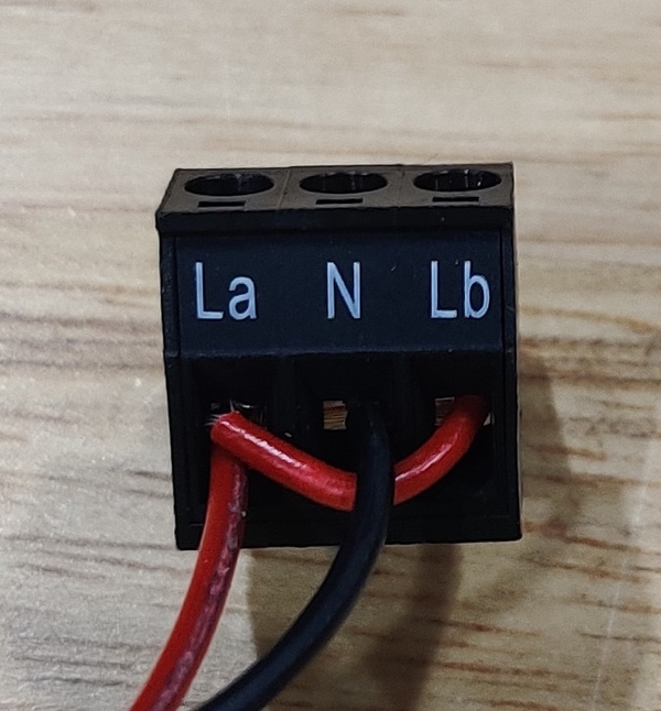
The Robot Signal Light (RSL) visually indicates what state of operation your robot is currently in. It is wired into the RSL port on the roboRIO. The Rookie Kit of Parts includes a 2-wire jumper cable that can have one end cut off and the blue Molex sample kit in the regular black Kit of Parts tote includes a 2-wire cable that has a connector on only one end.
The connector end of either cable is plugged into the RSL port with the red wire in the S position and the black wire in the ground position (the small lines in a triangular symbol). On the chopped off end of the cable, cut off a short section of red wire that will be used to connect the two outer La and Lb terminals. Strip off the ends of the wires and twist one end of the jumper cable with the red wire it was cut off from so that the two wires can be inserted into the same terminal on the RSL. The red wire can then be connected to either outer terminal with the jumper connecting it over to the other outer terminal as well. The black wire is connected to the center N terminal. The screws on the side of the terminal block will clamp down on the wire when tightened. The RSL can be mounted anywhere that satisfies the wording of rule R709, with our suggestion being the crossbar on the front of the KitBot mechanism structure.
Securing the Battery
Derived from the AM battery bracket manual.
“Insert the Battery into the Battery Tray with leads facing upward and on the same side as the SB Connector. Pull the strap around the center of the battery and underneath the spacer and clamp assembly.”
“Plug the SB connector from the battery into the SB connector mounted to the tray. Secure with a cable tie around both connectors through the small slot in the C Plate to ensure the battery will stay connected during match play.”
Double check that all wires are securely connected with no bare strands of wire showing and that red wires are in red receptacles and black wires are in black receptacles. The main breaker of the robot functions as the power switch, and pushing in the lever on the side of the switch turns it on. Before turning the robot on it is good practice to say “Clear!” and ensure others around the robot are clear of it as it could begin to move unexpectedly when turned on. Assuming everything is wired correctly, the PDH should have its battery level indicator light up, each motor controller should begin blinking, the roboRIO should begin to boot up with status lights, the radio should begin to boot up with blue status lights, and after a moment the robot signal light should turn solid orange. If it does not appear that a component is receiving power, check that its slot in the PDH has a breaker (or fuse, for the roboRIO and Radio Power Module) and that the wires are securely plugged in. After wiring, some control system components like the roboRIO and radio will need to be imaged with the correct firmware and the Spark Maxes will need their CAN ID numbers set.