Motor and Gearbox Assembly
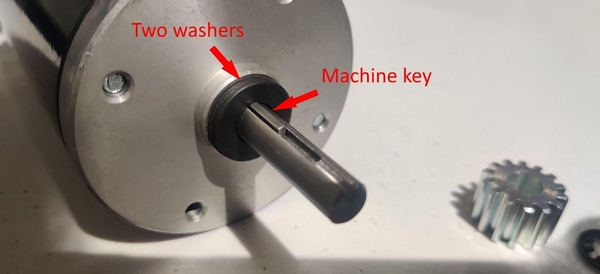
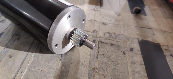
For each of your four drivetrain motors, place two 5/16” washers (am-1009a) onto the shaft. If your team is a rookie team, your kit of parts should include six CIM motors. If you are not a rookie team, your kit will contain only two CIM motors, so you will need to purchase two new motors or reuse two from a previous year (recommended). Two more CIM motors are also used in the KitBot launcher mechanism if your team plans on building it. Install a machine key into the slot in the motor shaft.
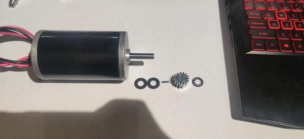
Slide a 14 tooth pinion gear (am-0034) onto the motor shaft, lining up the key with the gear’s keyway. Clip the stackup onto the motor shaft using an 8mm retaining clip (am-0033) with the teeth of the clip pointing inwards. Do not push the clip fully down against the gear or it can cause the motor to bind.
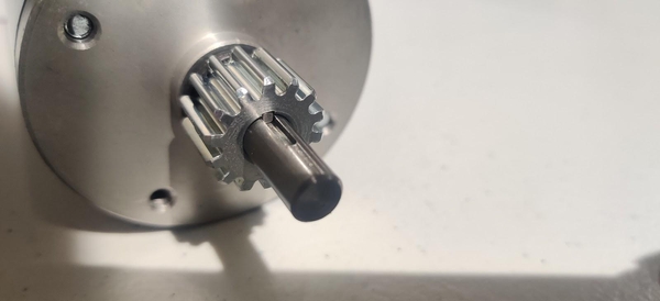
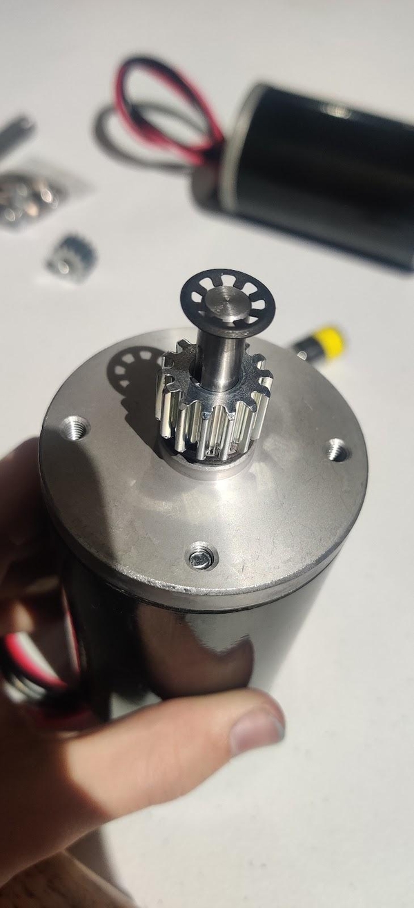
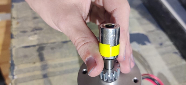
Placing a 7/16” or 3/8” socket over the clip and hitting it with a mallet can assist in pushing the clip down onto the shaft. This can be fairly difficult to do, and if the clip becomes deformed you should try to flatten it back out.
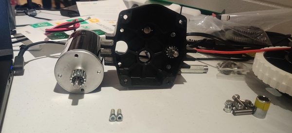
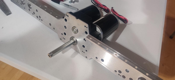
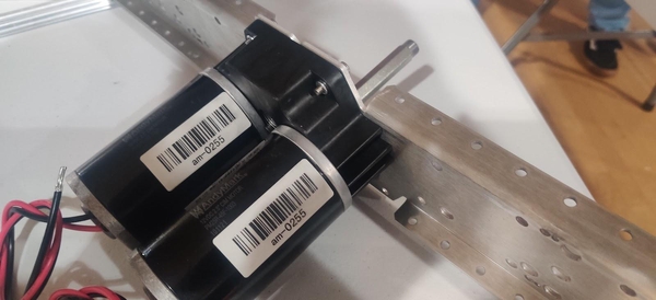
Screw two of the motors into each Toughbox Mini S gearbox housing (am-0650). The output shafts of the motors line up with the two larger holes in the gearbox housing and are screwed in using 10-32 x 0.625” bolts with thread lock already applied (am-1120) through the mounting holes above and below the input shafts and into the two mounting holes in the face of the motor. As these bolts approach fully tightened they become harder to turn. Make sure the bolts are actually fully tightened or the CIM motors will flex and rock around in the gearbox. If you can wiggle the CIM motors by hand then they need to be tightened more.
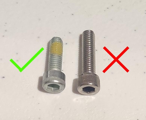
These bolts can be identified easily by the small patch of yellow or white thread lock on the threads of the bolt. Threadlocker is used on these bolts so that the motors do not vibrate them free over time. They are also shorter than the 10-32 x 0.75” bolts that come in the same bag.
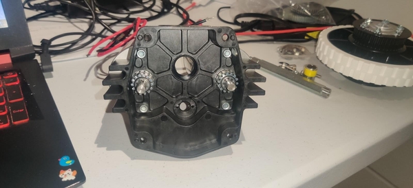
CIMs have four holes in the face of the motor. Two already have long cross-head screws inserted from the bottom of the motor to hold them together, so you may have to rotate the CIM motors around until the two open holes line up with the mounting holes in the gearbox housing.
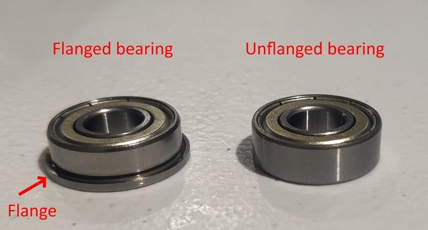
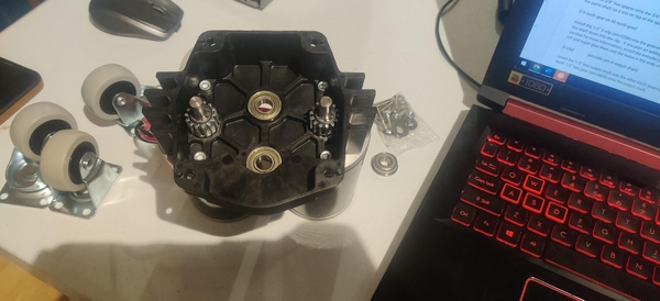
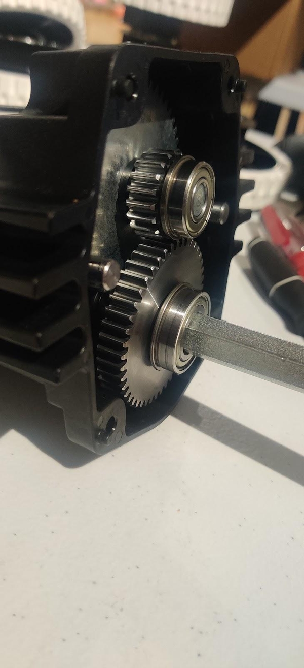
Two of the bearings used in the Toughbox have flanges while the other two do not. A flanged bearing has a small ring extending around it as shown below.
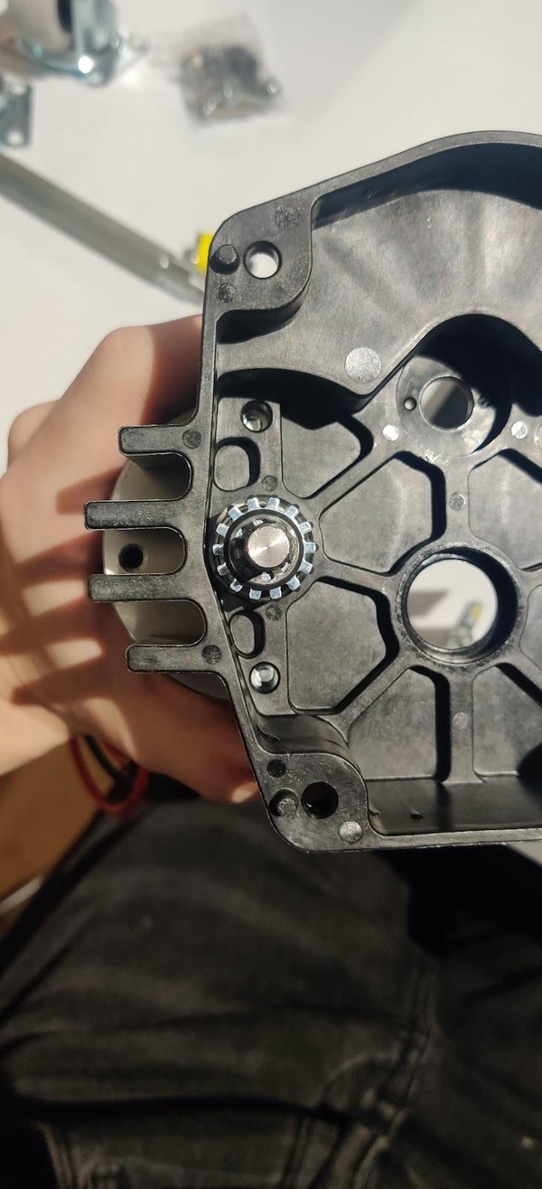
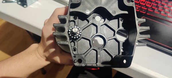
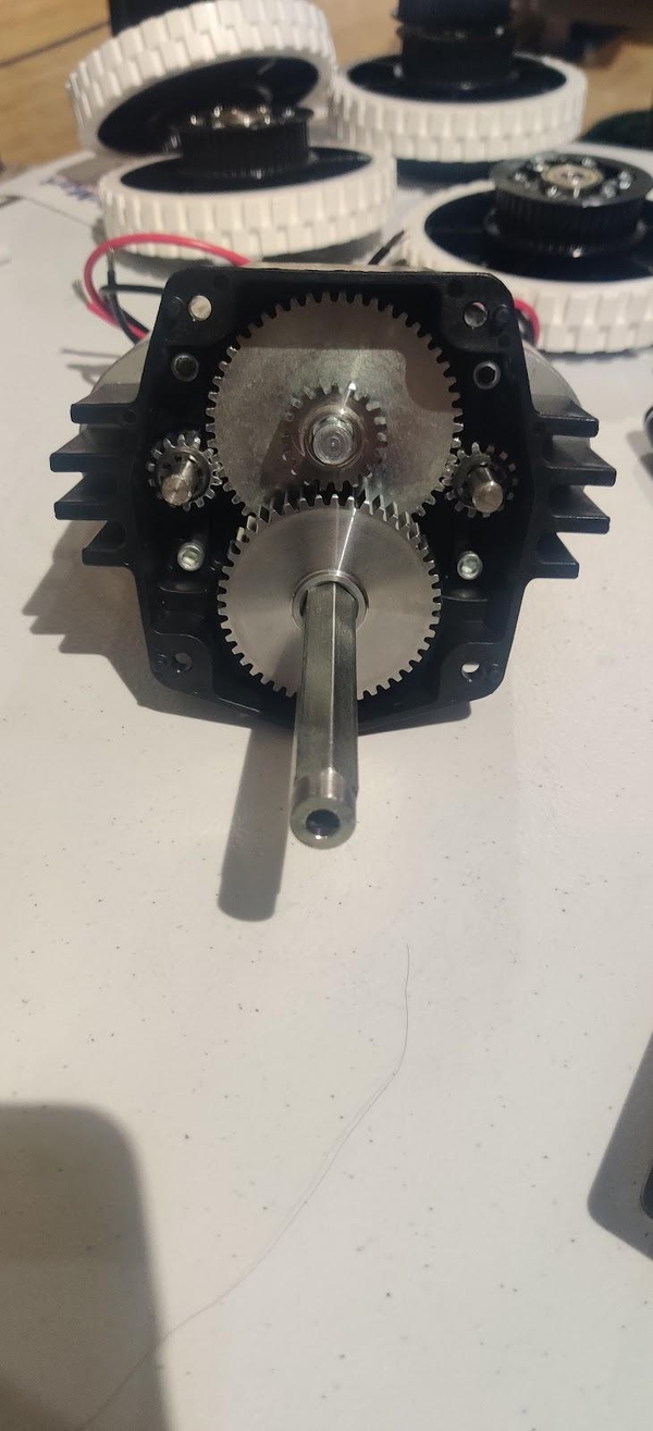
Press two R6ZZ 3/8” round inner diameter bearings (am-0516) without flanges into the two center holes of the Toughbox Mini S housing. Insert the Toughbox small 3/8” hex shaft (am-0152) into the bearing closer to the flat end of the gearbox housing.
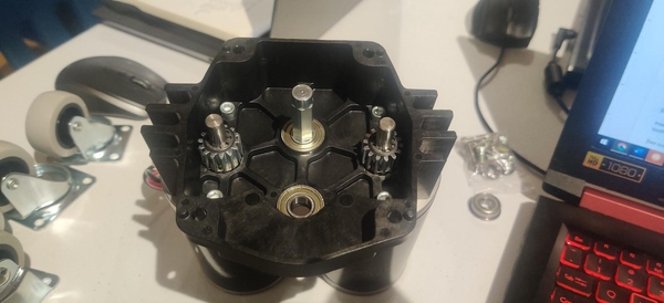
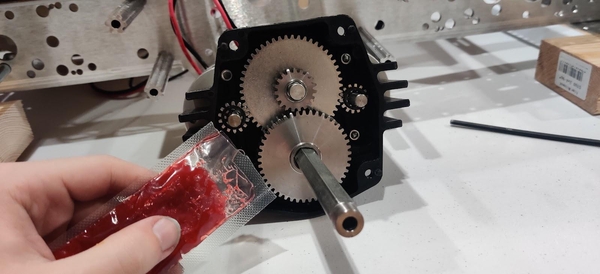
Take the 3/8” hex 50 tooth gear (am-4720) and place it onto the 3/8” hex shaft. Then add the 19 tooth gear onto the same shaft so it sits on top of the 50 tooth gear.
Install the 1/2” E-clip (am-0206) into the groove in the Toughbox 1/2” hex output shaft (am-4722) by pushing the shaft down onto the clip.
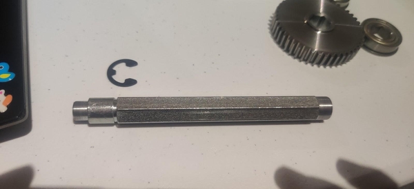
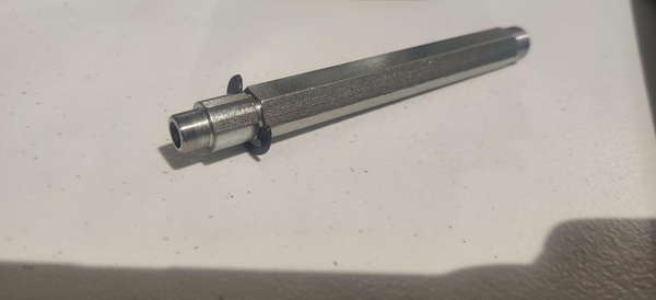
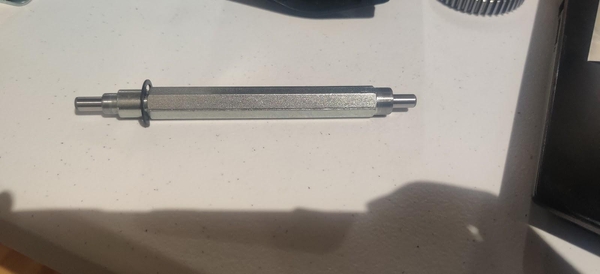
If you plan on adding encoders to the KitBot, install the encoder pin shafts (am-1323) into the 1/2” hex output shaft now. Clean the pins off and super glue them into the holes in the ends of each 1/2” hex output shaft. Let them dry before continuing.
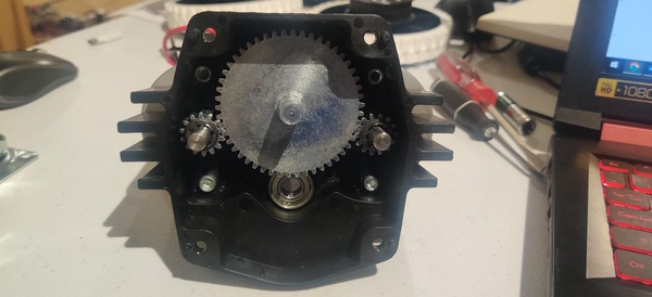
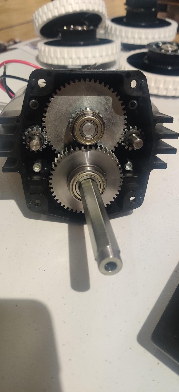
Insert the 1/2” hex output shaft into the other R6ZZ bearing with the E-clip closer to the bearing. Place the 45 tooth 1/2” hex gear (am-4712) onto the output shaft.
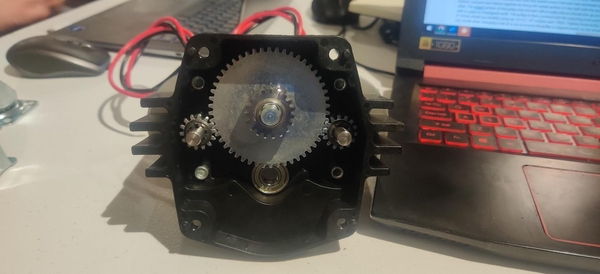
Place the FRZ6ZZ 3/8” round center bearing with flange (am-0028) onto the other end of the short 3/8” hex shaft on top of the 19 tooth gear, with the flange of the bearing closer to the gear. Place the FR8ZZ-HexHD 1/2” hex center bearing with flange on the 1/2” hex output shaft on top of the 45 tooth gear, with the flange of the bearing closer to the gear.
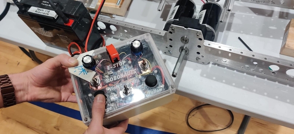
If your team has a convenient way to run your drivetrain motors now, such as an electronics test bed with motor controllers or other method of power delivery or by plugging the motors to a previous year’s robot, it is recommended that you run in the gearbox “dry” for thirty minutes at this point. Before greasing the gears inside, attach the Toughbox Mini S to the Chassis Inside Plate as described below and secure it. Connect whatever method you have for powering the motors and turn it on, leaving it to run in for thirty minutes. They may start out loud but should not produce an ear-splitting “squeal” or “screech.”
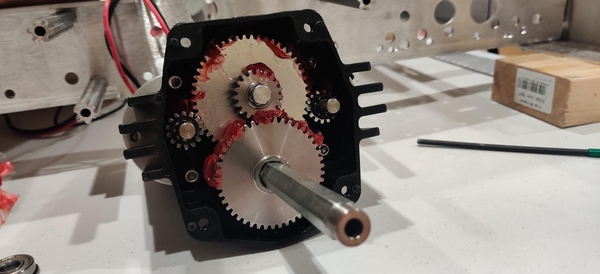
Once you have run in your gearbox, or if you do not have a convenient way to run in your gearboxes right now, apply red tacky grease (am-2768) to all the teeth of the gears. The flat surfaces of the gears are not as important as well-greasing the teeth where the gears actually mesh, and as the gearbox runs it will distribute the grease further.
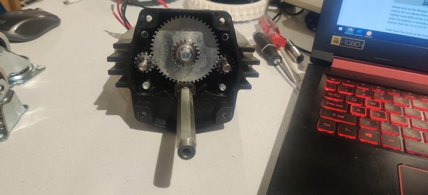
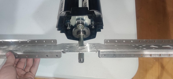
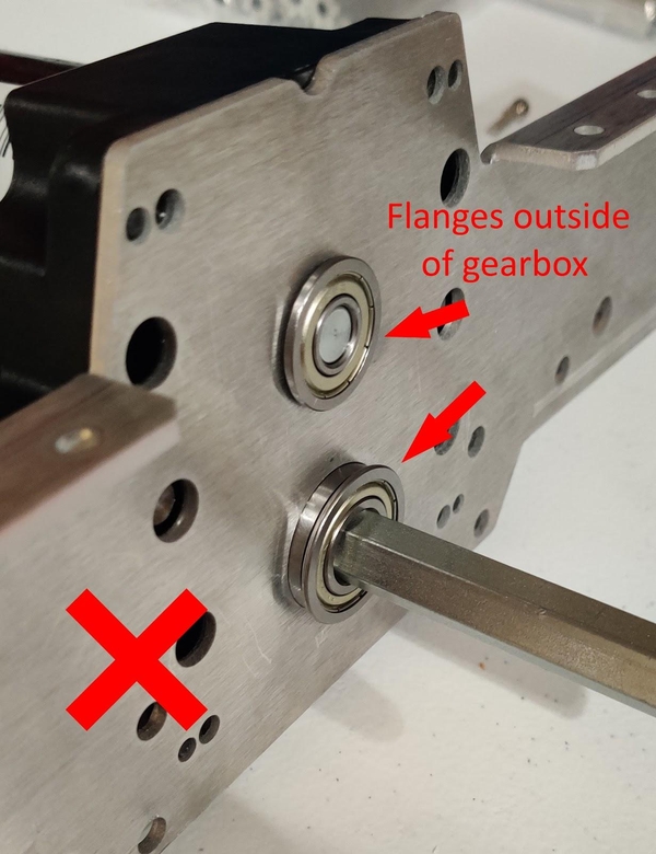
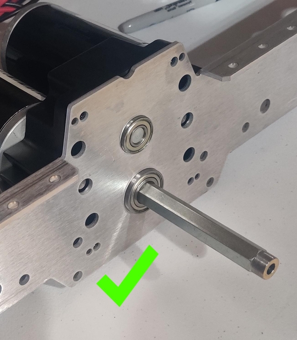
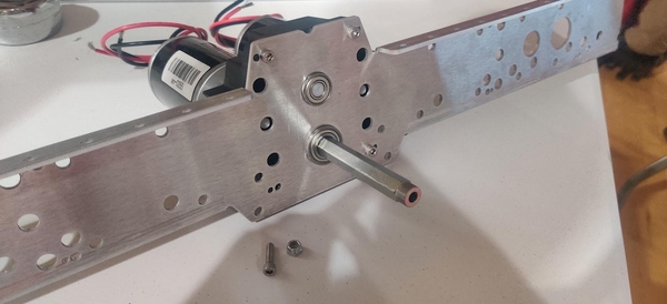
(Re)attach the Toughbox Mini S to the Chassis Inside Plate of the chassis using four 10-32 x 0.75” bolts (am-1047) and four 10-32 Nylock nuts (am-1042). The flat side of the gearbox lines up with the shorter side of the roughly trapezoidal gearbox mounting area in the center of the Chassis Inside Plates and the tapered side of the gearbox mates with the longer side of the trapezoid. The flanges on the Chassis Inside Plates should face away from the gearbox on the flat side (the top of the gearbox) and towards the gearbox on the tapered side (the bottom of the gearbox).
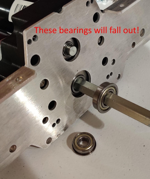
Make sure both of the flanged bearings are correctly “trapped” inside the gearbox by already being installed on the shafts when the gearbox is pushed into the Chassis Inside Plate - taking them out of the gearbox, inserting the gearbox’s shafts through the holes, and then sliding the bearings onto the shafts from the other side of the Chassis Inside Plate will leave the bearings able to fall out.
If the bearings do not want to fit in the chassis holes, they can be arbor pressed into place (be sure to get the flange on the correct side of the Chassis Inside Plate so that the flange will end up inside the gearbox!) or the holes can be enlarged slightly with a deburring tool.
The 10-32 x 0.75” bolts should be inserted into the Chassis Inside Plate and through the gearbox casing with the 10-32 Nylock nuts inserted into the hexagonal holes in the back of the gearbox casing.
Complete these steps with both Toughboxes, affixing one to each Chassis Inside Plate.