Everybot Roller Claw
Roller Claw Architecture
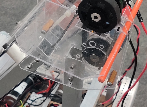
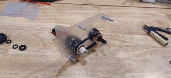
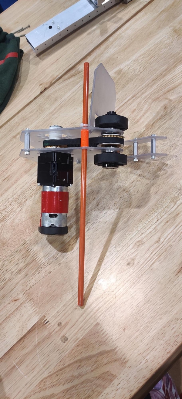
The Everybot roller claw uses a motor and pulley assembly and small compliant “squishy” wheels in a polycarbonate claw to intake a Note from the Source, store it when traveling across the field, and score it into the Amp.
The Everybot’s claw mechanisms can be adapted for a variety of different robot designs other than the KitBot or the “full” Everybot. A hole pattern that lines up with the KitBot launcher mechanism is included, but additional holes can be added or match-drilled into a different support structure. Please visit the Everybot Discord if you have specific issues or questions about using the claw in a different robot design.
Required Tools
- 3/8” wrench or T-handle
- 5/32” Allen wrench or ratchet
- Hacksaw or bandsaw
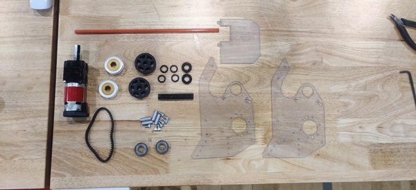
Roller Claw Materials
- Qty(1) x 775-class motor (RedLine, 775pro)
- Qty(1) x ~16:1 small planetary gearbox
- Qty(2) x Roller Claw Plates
- Qty(1) x Roller Claw Side Plate
- Qty(3) x Small Zip Ties
- Qty(4) x 1” long 10-32 standoffs
- Qty(8) x 0.5” long 10-32 bolts
- Qty(4) x 10-32 1.5” bolts
- Qty(1) x Fiberglass Driveway Marker
- Qty(2) x 2” “Squish”/Compliant Wheel
- Qty(2) x 24 Tooth HTD Pulley
- Qty(1) x 9mm 60 Tooth HTD Belt
- Qty(2) x 1/2” Hex Bearings (Round 13.75mm bearings can be used with rounded 1/2” hex shaft)
- Qty(2) x 1/2” Hex Shaft Collars
- Qty(4) x 1/8” (0.125”) 1/2” Hex Spacers
Cut components:
- Qty(1) x 2.75” long 1/2” Hex Shaft
Roller Claw Machining
A 2.75” long 1/2” hex shaft is used to run the roller claw’s two compliant “squishy” wheels. The roller claw mounts onto the KitBot superstructure in place of one of the corner gussets provided in the Kit of Parts to hold the superstructure together, so no box tube machining is necessary if building the Everybot from completed KitBot.
Cut a 14” section from the fiberglass driveway marker to use as a support for the Note in the roller claw.
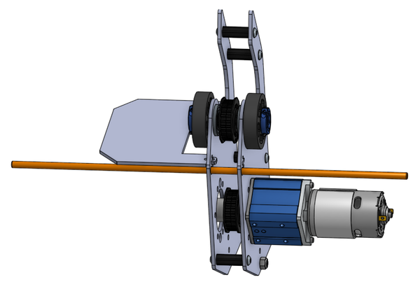
Roller Claw Gearbox and Motor
The Everybot roller claw gearbox is a small planetary gearbox with a ratio around 16:1. The Everybot roller claw plates have mounting holes for 775Sport, Max Planetary, and VersaPlanetary gearboxes. A 775-class motor like a RedLine or 775pro is recommended for its relatively small size and weight.
A NEO 550 could also be used but the motor controller would need to be relocated relatively close to the motor to be able to plug in the hall effect sensor cable and require power and CAN extension cables to the motor controller itself. Due to the lower speed of the NEO 550, a gearbox closer to a 10:1 would be preferred. 9:1 and 12:1 are both common gearbox options that will work. Make sure your gearbox choice works with (or can be adapted for) the NEO 550 (check the product page and manual usually found there carefully).
Roller Claw Assembly
If you do not have access to a CNC mill, router, waterjet, or other similar computerized manufacturing process it is recommended that your team purchase a pair of roller claw side plates from one of the manufacturers that have agreed to produce and sell them directly to teams. A DXF of these side plates can be found here with the horizontal support plate here.
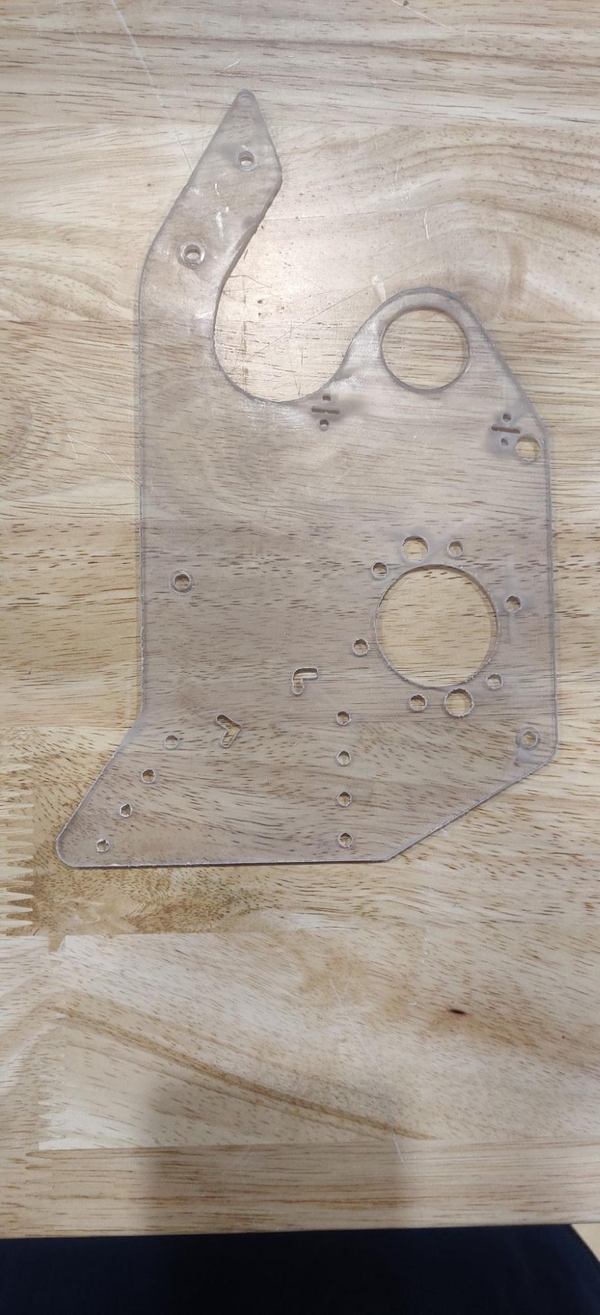
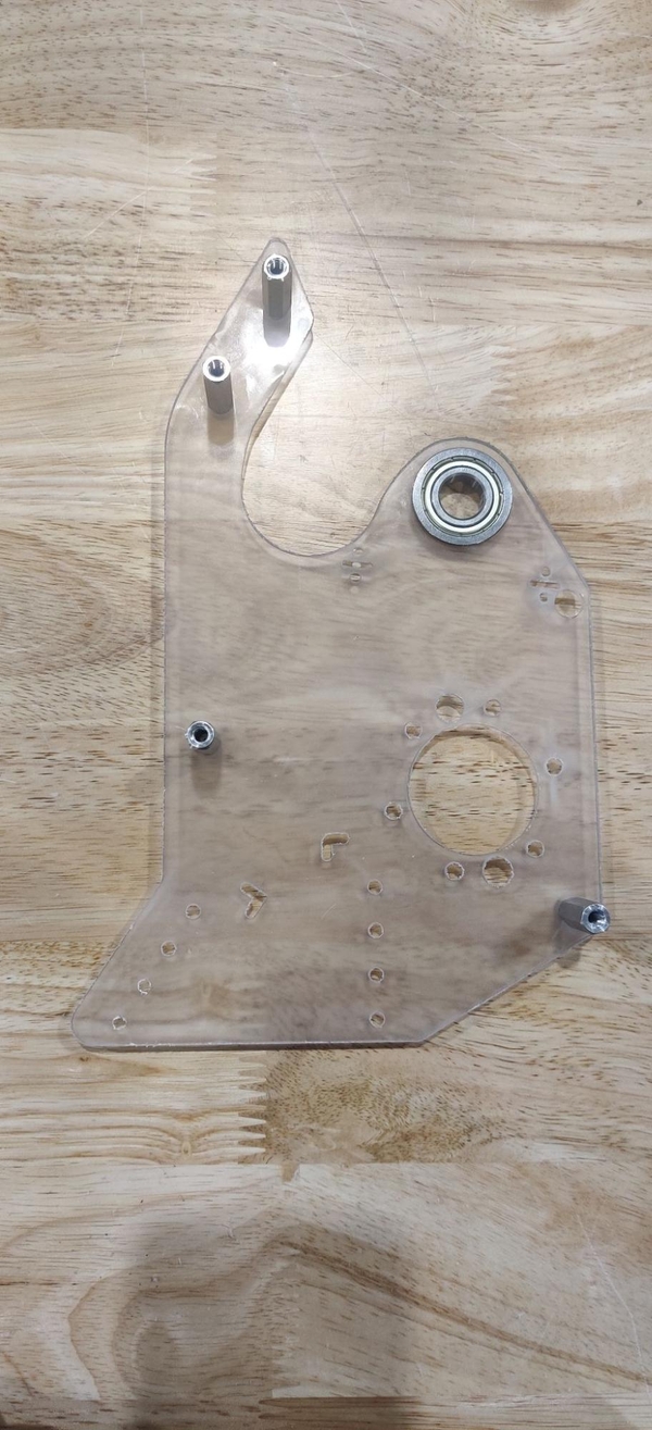
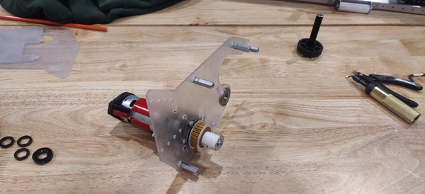
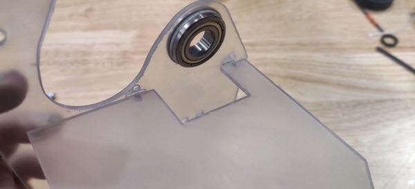
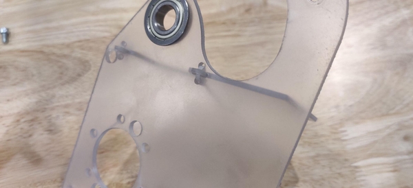
Start with one of the claw plates sitting flat with the claw opening to the right. Install four 1” standoffs sticking up from the plate in the marked holes using 10-32 1/2” long bolts matching the threading of your standoffs. These standoffs will hold the two plates apart at the correct distance. Insert a flanged 1/2” hex bearing into the roller claw plate with the flange on the same side as the standoffs.
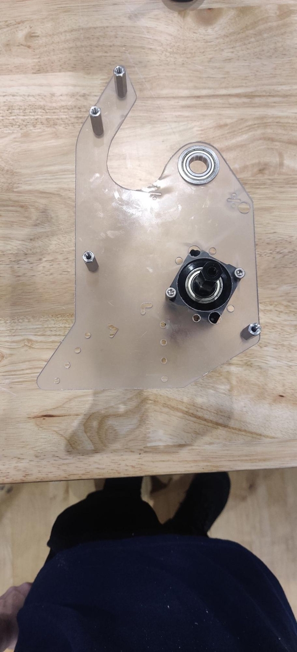
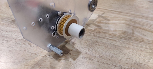
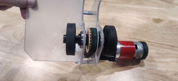
Insert the gearbox assembly into the larger hole so the gearbox and motor stick out the opposite direction from the standoffs and screw it in place using bolts suitable for face mounting your gearbox of choice (10-32 1/2” bolts should work). Insert a 1/8” hex spacer and a 24 tooth pulley over the end of the gearbox output shaft (If your pulley is able to rub against the roller claw side plate, add a second 1/8” spacer).
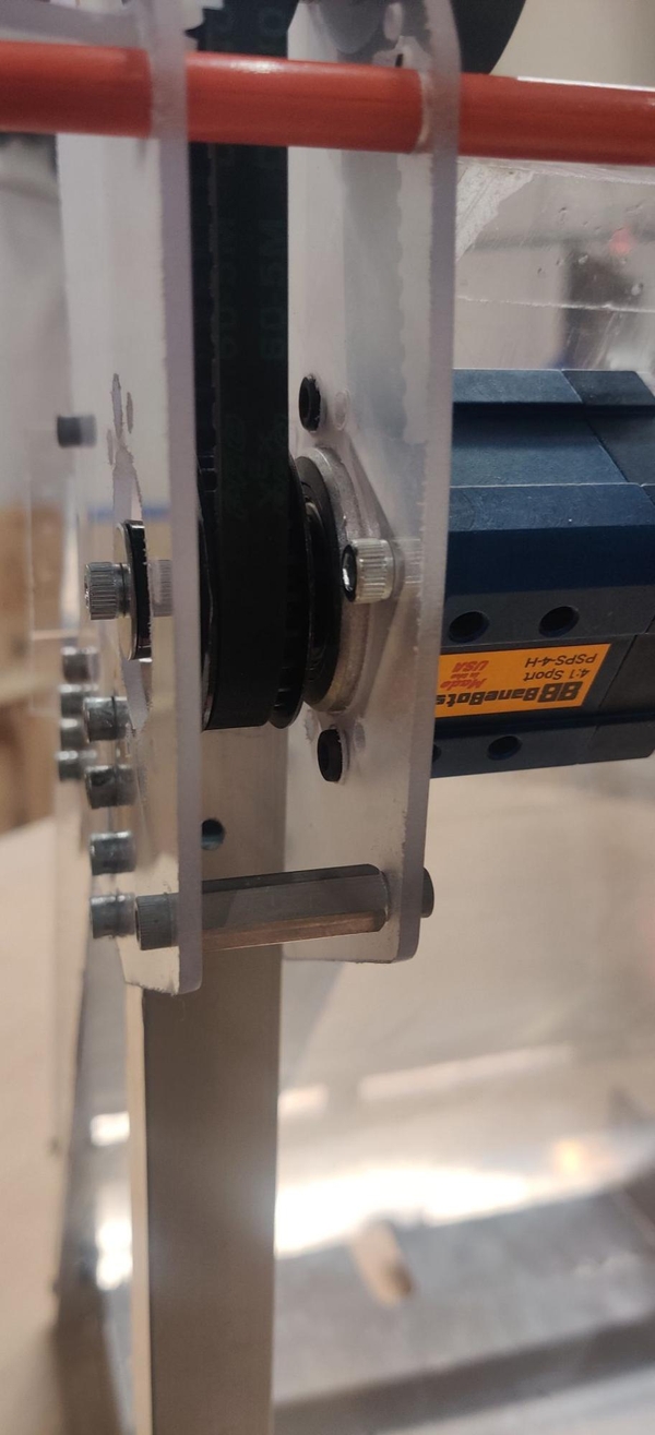
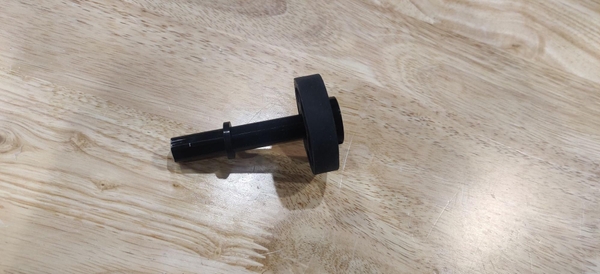
Cut from PVC, 3D print, or otherwise procure a spacer the correct length to cover the rest of your gearbox’s output shaft minus the width of a shaft collar. Add the spacer and cap off the shaft with shaft collar (we used a washer and bolt, but these larger washers are not used elsewhere on the robot. If your team has some larger washers, a washer and bolt can be used instead of an additional shaft collar).
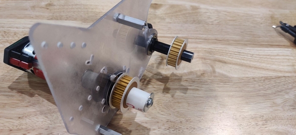
Install a shaft collar on the end of the 2.75” hex shaft, as close to the end as you can reasonably get it. Flex one of the squish wheels over the short shaft and work it down until it sits against the shaft collar and add a 0.125” spacer.
Insert the hex shaft into the bearing so the wheel and spacer are on the outside of the plate. Add a 1/8” spacer, second 24 tooth pulley, and additional 1/8” spacer over the end of the shaft and loop the 60 tooth belt over and around both pulleys.
Position the other roller claw plate so it opens up to the left and install a 1/2” hex bearing. Flip the claw over and position the horizontal support plate so it is in the designated slots and the zip tie holes line up.
Take two small zip ties and feed them through the four holes at each joint. Leave the front zip tie slightly loose so that another zip tie can be fed through it to hold the fiberglass rod in place later.
Place the second roller claw plate so the roller shaft fits through the bearing. Screw in the other side of the standoffs using more 1/2” bolts. Add another 0.125” spacer and second squish wheel and cap off the axle with another shaft collar.
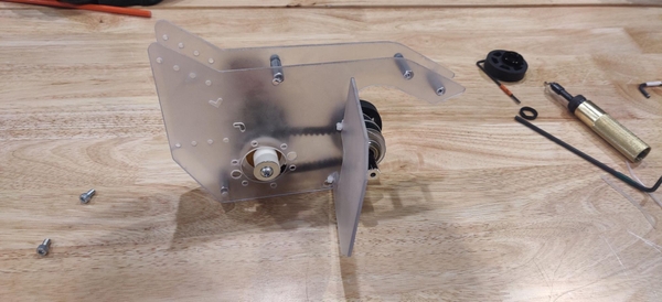
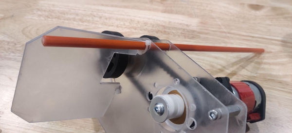
Push the 14” fiberglass rod through its designated holes. Use a small zip tie to tie the fiberglass rod to the zip tie holding the front of the horizontal support plate. A strip of tape is wound around the fiberglass rod between the two plates to hold it in place.
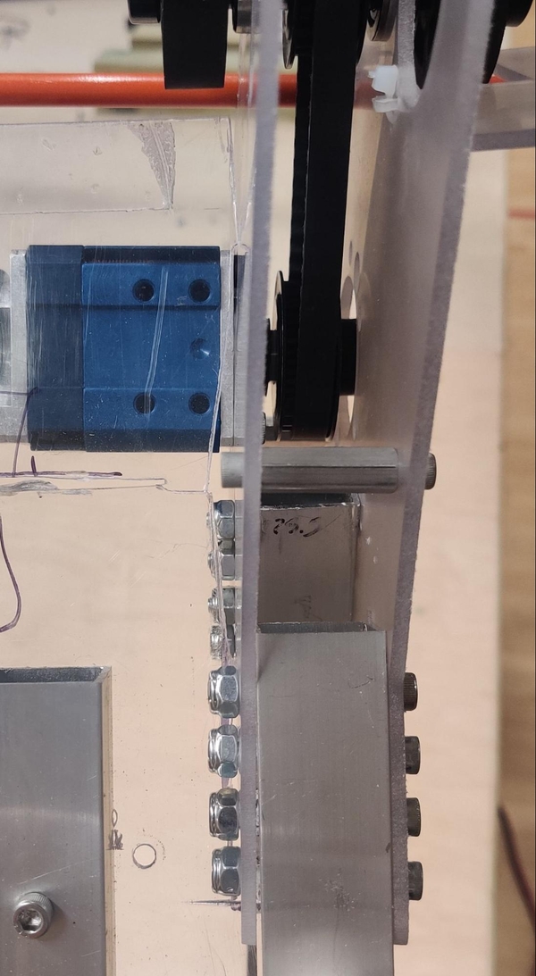
The Everybot roller claw attaches in place of the bracket in the upper right corner of the KitBot launcher mechanism. Remove the bolts or rivets holding it in place and remove the gusset. Cut about an inch off of the right side of the lower launcher plate so that there is room to install it. Position the two plates of the roller claw in position over the same holes, using the alignment slots in the plates to ensure it is positioned correctly. Attach the claw with at least four 10-32 1-1/2” bolts, two in each support, through both plates and both pieces of box tube.