Everybot Climber
Climber Architecture
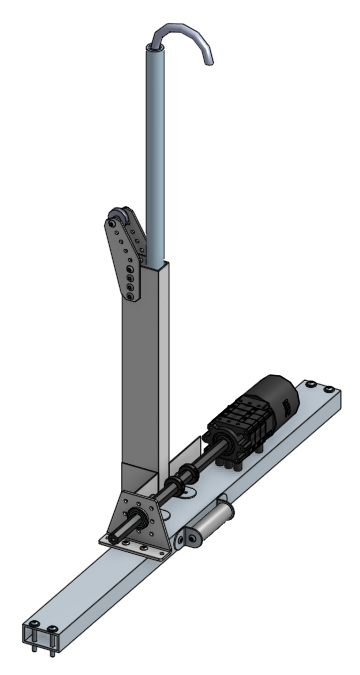
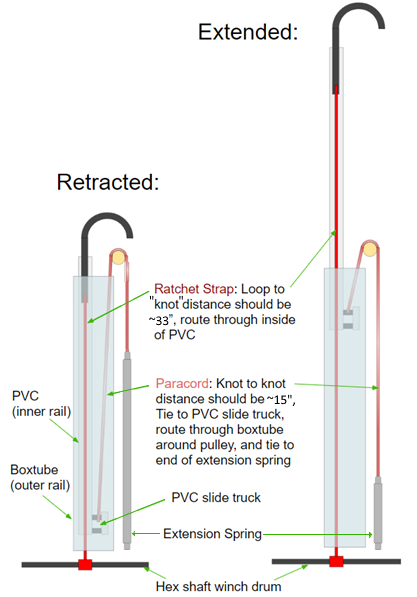
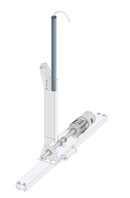
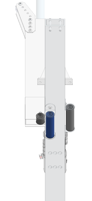
The Everybot climber uses a 2” x 1” box tube as the outer tube of a telescoping system to lift a hook up to the Stage chain. The inner tube is a 1/2” schedule 40 PVC pipe, pulled upward by extension springs routed around the top of the robot by paracord. The height restrictions of this year’s game allow for the climber to start the match already extended upwards and remain that way for the entire match until the robot goes to hang at the end of the match, where the winch winds the ratchet strap up and pulls the hook down (and itself up). The spring pulls the hook back up when the winch unwinds, allowing the robot to retry a missed climb.
A similar mechanism with different dimensions was used on the 2020 Everybot.
The Everybot’s climbing mechanisms can be adapted for a variety of different robot designs other than the KitBot or the “full” Everybot. Considerations may need to be made for the location of the center of gravity of your particular design and how the robot will tilt when the climber begins to lift it. Please visit the Everybot Discord if you have specific issues or questions.
Required Tools
- 3/8” wrench or T-handle
- 5/32” Allen wrench or ratchet
- Drill press (preferred) or hand drill
- Band saw (preferred) or other type of saw
- Vise (ideal)
Climber Materials
Climber:
- Qty(1) x 1” Wide Ratchet Strap (>3 ft long)
- Qty(1) x Spool of 1/8” Paracord
- Qty(1) x 6” Black Spring Link (Carabiner)
- Qty(1) x 1-1/4” Patio Roller Kit
- Qty(1) x Roll of Linerless Rubber Splicing Tape
- Qty(1) x Everbuilt 4.5” Extension Springs (comes in 4 pack with 6.5” springs)
- Qty(2) x TP 3-1/8 in. x 7 in. 20-Gauge Galvanized Tie Plate or larger 90° gusset
- Qty(2) x TP 3-1/8 in. x 7 in. 20-Gauge Galvanized Tie Plate or angled gusset (~135-150°)
- Qty(1) x 2” 10-32 or 8-32 standoff
- Qty(1) x 3” 10-32 or 8-32 standoff
- Qty(4) x 0.5” 10-32 or 8-32 bolts (matching standoffs used)
Winch:
- Qty(1) x NEO motor (or CIM, MiniCIM, etc)
- Qty(1) x 64:1 to 100:1 gearbox (64:1 - 80:1 probably preferred for speed and strength)
- Qty x Gearbox and Support Plate Spacers (if necessary)
- Qty(1) x 1/2” Hex Shaft Coupler (if necessary)
- Qty(4) x Bolts suitable for mounting gearbox
- Qty(2) x 1/2” Hex Collar (two-piece type preferred for at least two)
- Qty(1) x 1/2” Hex Bearing
- Qty(1) x Bearing Support Plate
- Qty(2-4) x Bolts suitable for mounting Bearing Support Plate (10-32 1.5” probably)
- Qty(6) x 10-32 1.5” Bolts
- Qty x #10 washers (4 + quantity for gearbox spacers if not using nylon or similar spacers)
Cut components:
- Qty(1) x 04_Climber_PVC_14"
- Qty(1) x 04_Climber_PVC_Holder
- Qty(1) x 04_Climber_Mount_Beam
- Qty(2) x 1/2” diameter 3” long PVC roller
- Qty(1) x 1/2” Hex Shaft 10” to 12” long
Climber Machining
The climber is made from two pieces of 1x2 box tube, some sections of PVC, and some hex shaft, brackets, and whatever motor and gearbox your team has selected. If you are using the suggested pre-drilled box tube, you will not have to add any additional holes but a few holes may need to be widened.
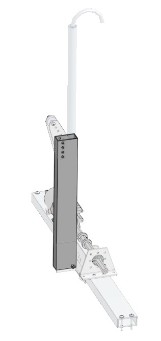
04_Climber_PVC_Holder is the upright portion of the climber and is 14 inches long and cut from the thinner 1/16” box tube. This box tube will hold the 04_Climber_PVC_14" slider.
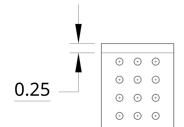
04_Climber_Mount_Beam is the horizontal portion of the climber that mounts to the chassis and holds the gearbox and winch for the climber as well as guides for the ratchet strap. It is 27 inches long and cut from the thicker 1/8” thick box tube. Ideally, this component is made from one of the styles of pre-machined box tub with a hole pattern in it from the factory. If you have this pre-drilled style of box tube, cut it down to 27 inches so that there is a complete set of holes centered 0.25” in from each end (these holes will be used to attach the climber to the frame of the chassis).
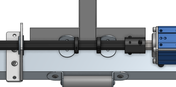
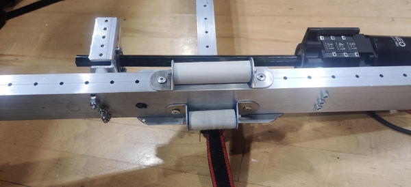
The positioning of the gearbox and winch support and the two 3” PVC spacers is shown below. The winch and spacers will not be perfectly centered as a result of the hole pattern but as long as the ratchet strap rides over the spacers and up to the winch without pulling to the right or left this will not matter.
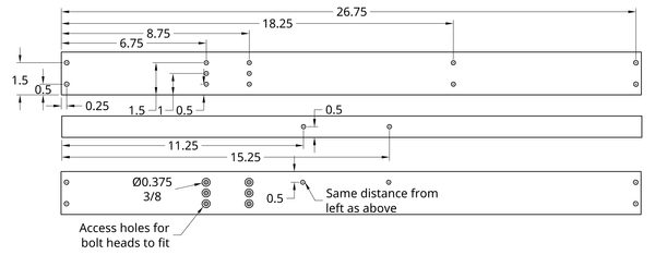
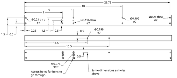
If you are not using pre-patterned box tube, below is a part drawing showing the location of holes for the chassis side rail mounting points, PVC spacers, and suggested gearbox and bearing support locations. The necessity of these holes varies with the exact style of gearbox your team is using (there is no central mounting holes on the sides of CIMSport and VersaPlanetaries, for example). These holes can be properly centered compared to the offset premachined holes above. The exact positioning is less important than making sure the gearbox is well-supported and that the motor and hex shaft are not hanging over outside of the frame perimeter. These gearbox mounting holes should be drilled out to 3/8” on just the bottom face of the box tube so the entire head of the 10-32 bolts used to attach the gearbox can fit freely past the bottom face and clamp the gearbox to just the top face.
Longer (~2”) bolts could also be used to mount through both faces of the box tube, but these bolts are not used elsewhere on the Everybot and could crush the box tube if overtightened. If your team prefers, and has some two inch or so 10-32s, you can try mounting the gearbox with bolts through the entire box tube.
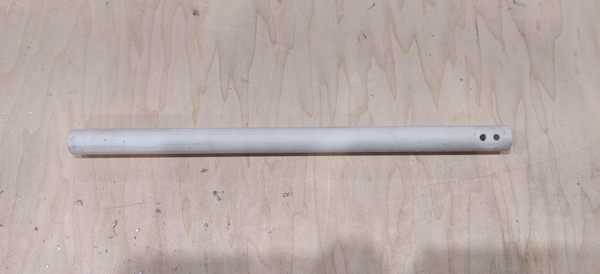
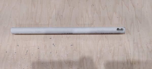
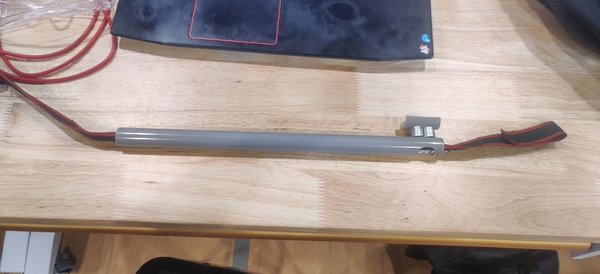
04_Climber_PVC_14” is, as the name suggests, a 14” section of 1/2” schedule 40 PVC. This is the extending section of the climber that the carabiner hook rides in.
An inch long section of PVC is cut in half and forms part of the sliding mechanism with 04_Climber_PVC_14”.
Three PVC spacers are used to guide the ratchet strap around the bottom of the climber and to the winch. Two are three inches long and one is about 0.8” to fit inside the 04_Climber_PVC_Holder (manufacture it to fit snugly inside your box tube for 04_Climber_PVC_Holder). (We used a 2” and 3” roller, but the exact size does not really matter as long as it is wide enough for the ratchet strap plus some travel room side-to-side).
A 10 to 12 inch section of hex shaft will be used for the winch of the climber. If you are using a Max Planetary gearbox, one side of the shaft can be tapped for a 10-32 bolt to affix it to the MAX Planetary output stage. Alternatively, a shaft coupler can be used with the provided output shaft of the Max Planetary. A shaft coupler is also required for the AndyMark CIM Sport gearbox as well as the VersaPlanetary if using the 1/2” hex output instead of the universal female output shaft.
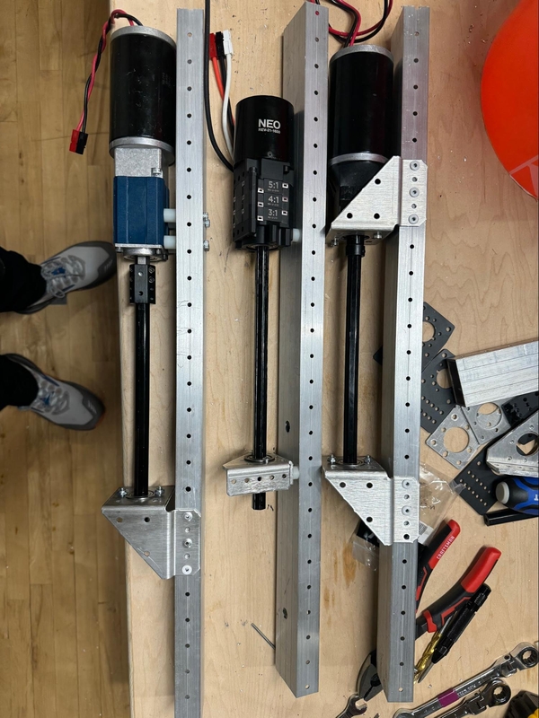
Climber Gearbox and Motor
The climber gearbox can be made from a variety of common FRC gearboxes and powered by a range of motors. CIM Sport, MAX Planetary, and VersaPlanetary gearboxes can all be used, with a handful of variances between setups. Different brackets can also be used to hold the 1/2” hex bearing used to support the other side of the climber winch shaft. As long as a decently long portion (four inches should be more than enough) of the shaft in the middle of the overall 04_Climber_Winch_Beam is open for the ratchet strap to be anchored around and held in place using split hex collars, the exact positioning of the gearbox and bearing support is not critical to functionality.
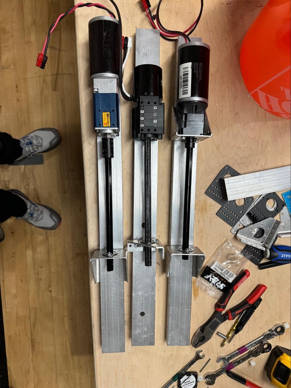
If you are using a REV MAX Planetary gearbox, tap one end of the winch hex shaft for a 10-32 bolt and bolt it into the output stage of the MAX Planetary. The gearbox will remain attached to the shaft throughout the rest of assembly, which is not shown in the photos below (we used a CIM Sport gearbox). Alternatively, a 1/2” hex shaft coupler can be used. A shaft coupler is required to connect the AndyMark CIM Sport gearbox to the hex shaft. A VersaPlanetary Universal Female Output Shaft and 1/2” hex adapter or a 1/2” hex output and 1/2” hex shaft coupler can be used with the VersaPlanetary. A VersaPlanetary Parallel Mount may be used to face mount the gearbox (as well as being one option for the bearing mount on the other side of the winch shaft).

Acceptable gear ratios for the climber gearbox start around 60:1 and go up from there. A gear ratio of around 60:1 or higher should be sufficient to hold the robot up with no ratcheting mechanism with the connected motor controller in brake mode.
Assemble the gearbox according to the manufacturer’s instructions, remembering to put the larger ratio cartridges closer to the motor for the MAX and Versa planetaries.
Any CIM or CIM-replacement (NEO, MiniCIM, etc) motor can easily drive the climber mechanism.
Climber Assembly
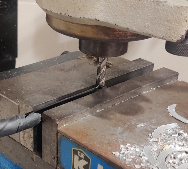
On one end of the 04_Climber_PVC_14" pipe drill two 13/64” holes approximately 1/2” apart. The best way to ensure these holes remain straight and go directly through the center of the pipe is to clamp it into a drill press and look from the side to ensure you will be drilling directly through the center of the pipe.
On one side of the PVC, drill these holes out to 3/8” to fit the heads of a 10-32 1” bolt. If desired, these two larger holes can be combined into one larger slot for convenience.
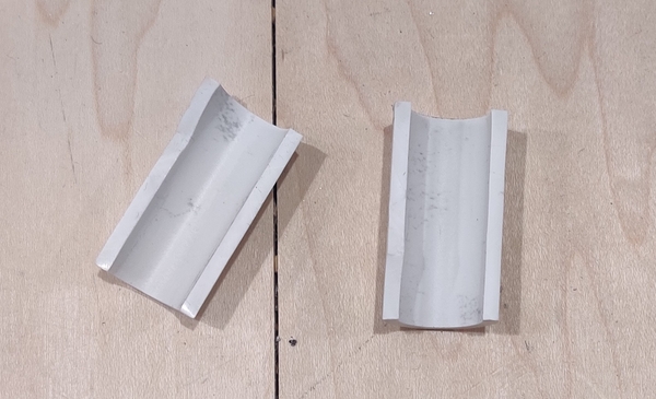
Cut an inch or so section of 1/2” PVC pipe and then cut it in half down the diameter of the pipe so it forms a half circle. Drill the same two 13/64 holes 1/2” apart in this small piece of PVC.

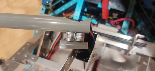
Insert two 10-32 1” bolts through the large holes in the 04_Climber_PVC_14" and stack up approximately 10 #10 washers on each bolt. Insert the cutoff half PVC section over the ends of the bolts so it curves away from the longer PVC pipe. Bolt the short section into place. This will form a “slider” that will ride inside the 04_Climber_PVC_Holder. Check that the slider does not bind up with the box tube and if necessary add or remove some washers from each bolt.
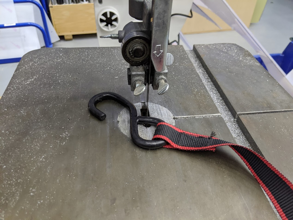
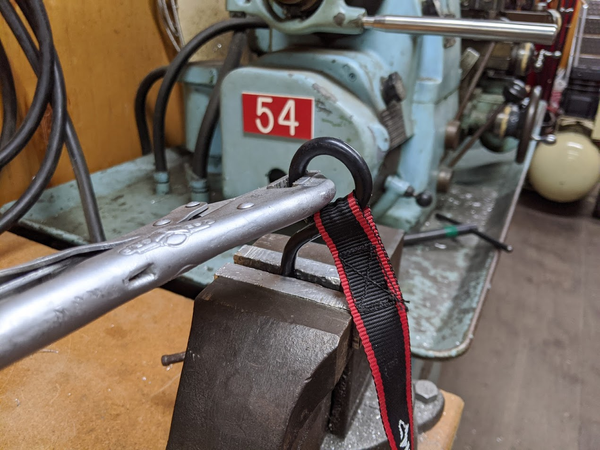
Cut the hook off the end of the ratchet strap using a bandsaw and vise grips or a hacksaw and a vise, or pull the loop of the hook open enough to be able to pull the strap out of the hook. Leave the pre-sewn loop in the end of the strap as it will be used to attach the ratchet strap to the winch hex shaft. Cut the ratchet strap down to about 35” long from the unlooped side, erroring on the side of being longer.
Feed the ratchet strap up through the 04_Climber_PVC_14" so the end with the loop ends up near the slider at the bottom of the 04_Climber_PVC_14" and the free end is sticking up out of the top of the PVC. Leave some slack on both ends so the strap does not accidentally pull back through the pipe.
Cut the carabiner hook off towards the bottom of the spring-loaded side of the carabiner, leaving a hook shape. This can also be done in a vise with a hacksaw.
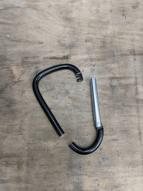
Mark a divet about half an inch up from the cutoff end of the carabiner.
Clamp the hook in a vise and drill out a ~9/32” hole at the marked location. Make sure to keep the hole relatively centered and straight so it does not break through the side of the carabiner.
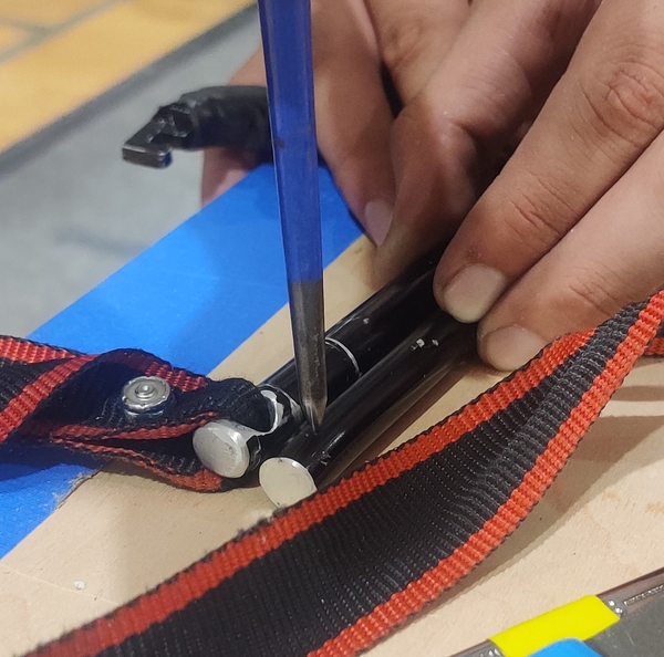
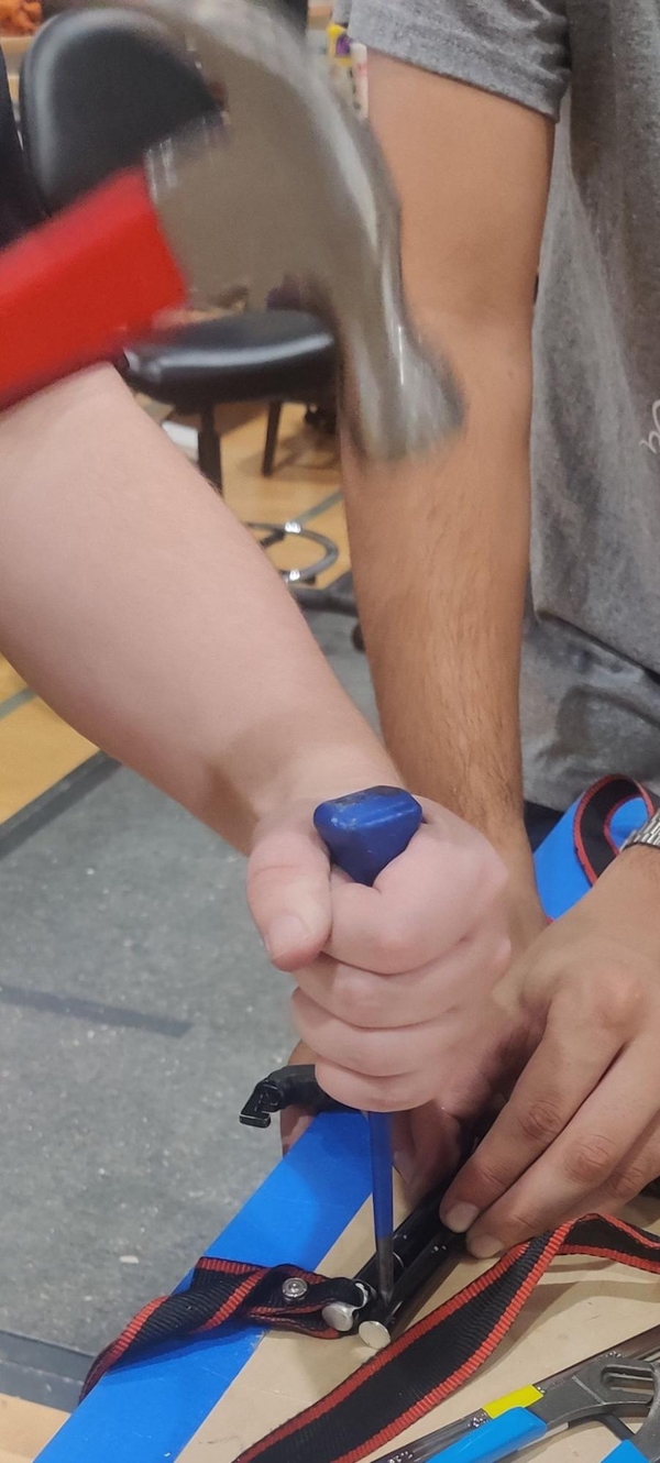
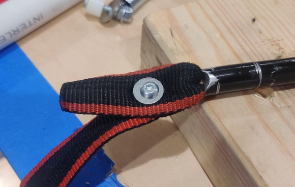
Feed the strap through the hole in the hook and loop it back through. Poke or drill a hole in the two layers of strap and bolt the two layers together with a button head 10-32 5/16” bolt with #10 washers on both sides so that the bolt does not pull through the strap. Wrap the hook with linerless rubber splicing tape to prevent it from slipping on the chain.
Tie one end of the paracord around the bolt and washer stackup in the PVC slider. Feed the assembly down through the 04_Climber_PVC_Holder so that the slider and looped end of the ratchet strap end up at the bottom of the box tube and the hook and the loose end of the paracord are hanging out of the top of the PVC and box tube.
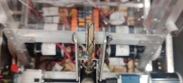
Thread the winch hex shaft through the ratchet strap loop. Later on this loop will be held in place to prevent it from just spinning freely around the shaft.
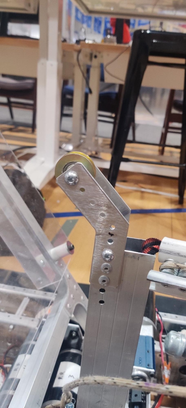
At the top of 04_Climber_PVC_Holder attach a pair of cut-off tie plates or angled gussets and install the patio door roller between them on a 10-32 1.5” bolt with two 0.3” spacers so that the paracord has a pulley to ride over. If you install a 10-32 1.5” bolt as the top mounting point in these brackets it will hold the climber slide inside the tube and prevent it from accidentally coming out, as well as making the slide a little bit more stable in the tube.
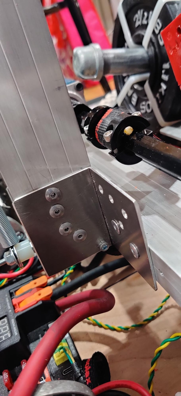
The 04_Climber_PVC_Holder can be attached to the 04_Climber_Mount_Beam using bent tie plates, purchased gussets, or angle stock with holes drilled through them. Be careful to hold the ratchet strap out of the way when drilling so it does not get drilled through or tangled up in the bit. The upright box tube does not actually support the weight of the robot when climbing, it only serves to keep the PVC slider and ratchet strap vertical, and once the ratchet strap is taught the weight of the robot is being transmitted through the strap. A 10-32 1.5” bolt with the ~0.8” PVC spacer cut previously at the bottom of the tube will help the ratchet strap roll around the bottom of the climber.
Construct the two other PVC spacers for the ratchet strap to ride around. We used a two inch and three inch spacer, but two three-inch spacers are recommended. The spacers have three inch long 10-32 standoffs inside with two 90 degree brackets bolted to each side with two 10-32 0.5” bolts. These spacers should ideally not roll.
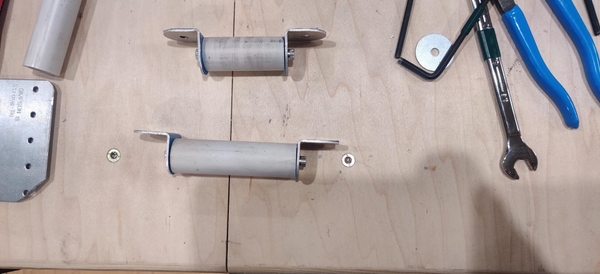
One spacer sits under the 04_Climber_Mount_Beam towards where the ratchet strap exits the box tube on the two inch face.The other spacer is mounted to the rear face of 04_Climber_Mount_Beam so the ratchet strap can be fed around it and to the winch mounted on the top. If you are using pre-patterned box tube, center the spacers as best you can in the existing holes so the ratchet strap will not hang over on either side. If not using pre-drilled tube, drill two #7 holes half an inch up from the front side of the box tube where the 04_Climber_PVC_Holder will be mounted that are four inches away from each other and rivet the brackets on the spacer into place. On the opposite side face from where the 04_Climber_PVC_Holder is mounted, drill out two #7 holes four inches apart and centered across the 1” face of the 04_Climber_Mount_Beam so the roller is approximately centered along the long face and is in line with the 04_Climber_PVC_Holder. Rivet the spacers into place.
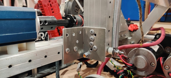
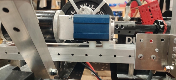
Whichever gearbox your team is using can also be bolted down to the 04_Climber_Mount_Beam. If you have not already done so, make sure the loop of the ratchet strap is through the winch hex shaft. If you are using pre-machines box tube, there should already be appropriate holes in a serviceable location on 04_Climber_Mount_Beam. Widen the holes on what will become the bottom face so that the bolts can be floated through the bottom face and clamp against just the top face. (Alternately, your team can use longer (~2”) bolts to mount the gearbox through both faces of the box tube, being careful to not crush the box tube inwards when tightening it) Add spacers or washers to the bolts to bring the gearbox up to an appropriate height to mount horizontally on the 04_Climber_Mount_Beam. An alternate gearbox mounting bracket may also be used for some gearboxes like the VersaPlanetary.

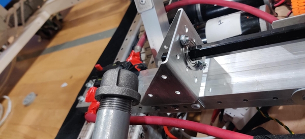
Whatever hex bearing support bracket your team has purchased or made can be installed towards the unsupported end of the hex shaft. Clamp the bracket in place and match drill out appropriate mounting holes if they do not already exist. Add spacers or washers if necessary to bring the hex bearing up to the correct height, insert the bearing over the hex shaft and into the hole, and trap it in place using a shaft collar, rivets, bolts, or similar means.
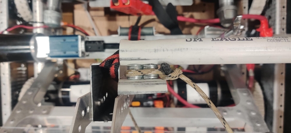
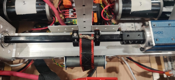
Position the loop of the ratchet strap on the hex shaft so it is in line with where it comes out of the tube. Cut a short piece of paracord wider than the width of the ratchet strap and sandwich it over the ratchet strap and between the hex shaft and two clamping hex shaft collars. This paracord will stop the ratchet strap from just spinning freely around the winch when the winch runs.
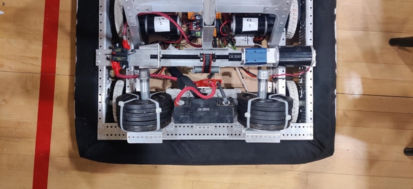
The 04_Climber_Mount_Beam is bolted to the frame using four 10-32 1-1/2 bolts, two on each side, in the 10th and 11th holes from the back of the chassis. Use #10 washers to help prevent these bolts from pulling through or crushing the box tube. If you are using pre-machines box tube, these holes should already be in place. If not, mark two holes an inch apart and half an inch in from either side of the two inch face that are 0.25” in from the open end. It may end up lining up better if you drill out the two holes on one side, bolt that side in place, and then match drill up through the bottom of the chassis, removing the climber assembly and drilling up through the top face if your drill can only reach the bottom face through the chassis.
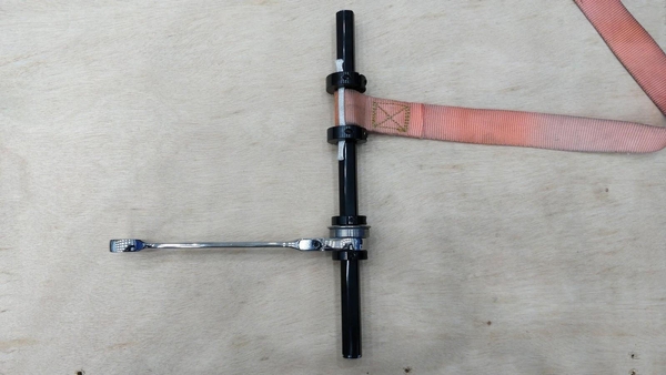
The climber motor is plugged into a motor controller that we positioned under the 04_Climber_Mount_Beam. In our provided code this is a Spark MAX with the CAN ID 7. If using the NEO in the Rookie kit of parts (or purchased separately), a Spark Max is required to control it and must be located close enough to plug in the hall effect sensor cable from the motor into the controller. When the motor controller is set to brake mode, we found that a CIM motor in a 64:1 CIMSport had sufficient resistance to hold the robot up without any ratcheting mechanism. If your robot droops down on the chain when powered on and in brake mode, a 1/2” ratcheting wrench (preferably with a reversible ratchet pawl so it is easier to reset) can be added to the hex shaft to hold the robot up when climbed, as long as you are careful to not continue to run the climber too far past its end of travel as the ratchet will begin to bind.
The winch should be unwound to the starting configuration after every match that a climb is attempted. Do not attempt to enable the robot directly after a match, please wait until you return to your pit. Whenever enabling the robot inside your pit, make sure to chock up the robot such that the wheels are not touching anything. Even if you do not expect to use the drivetrain, an accidental stick press or dropped controller could result in injury.