Chassis Overview
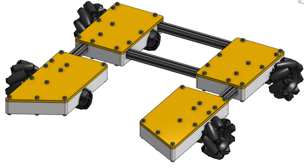
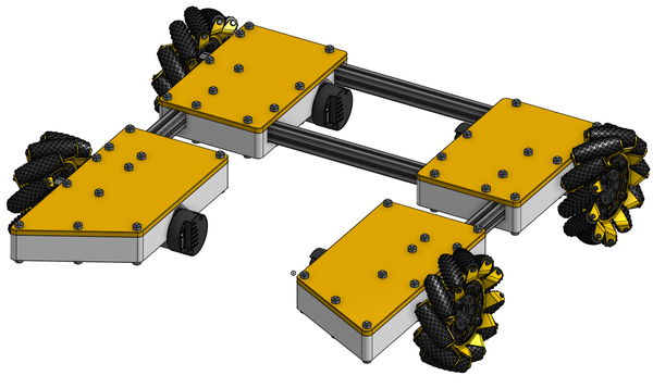
Similar to last season, we have our custom clamshell design. This design has been updated to allow for easier expansion and modifications.
Additionally, this year in an effort to expand our accessibility the Everybot has full support for the following vendor chassis:
We also offer partial support for the AM chassis, allowing for everything except the endgame:
This chassis guide is specifically dedicated to the Everybot custom 3D printed chassis, for construction of other chassis please follow the manufacturer’s instructions.
Custom Everybot Chassis Architecture
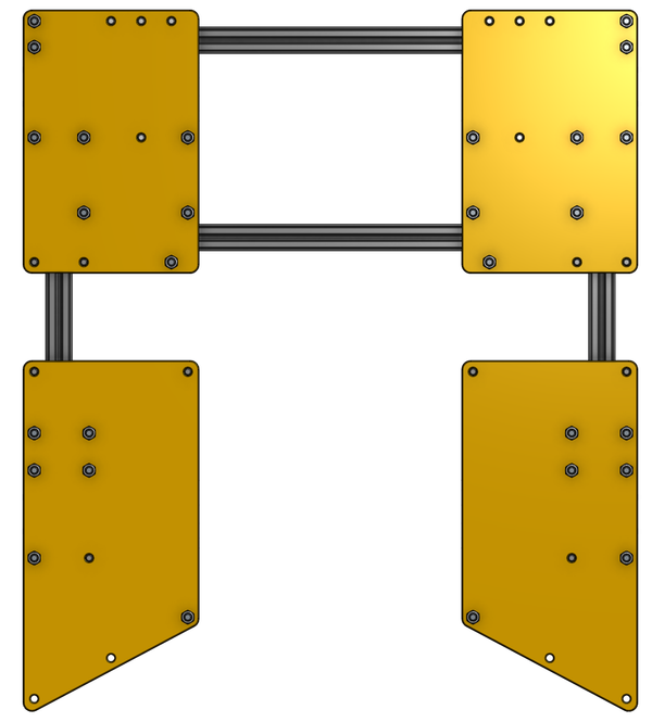
The Custom Everybot Chassis uses a 3D printed clamshell design for the drivebase. The clamshell parts are meant to clamp around the extrusion, eliminating the need to bolt directly to or through your desired extrusion. The chassis is designed to accommodate common drivetrain motor/gearbox combos. The drivebase also allows for an assortment of different wheel sizes, at the end of the Chassis Section, there is a table of motors, output shafts, and required hardware for different wheels.
The basic assembly steps are:
- Obtain/create of the following 3D printed parts:
- Qty(1) x 01_Chassis_Back_Right_Bottom
- Qty(1) x 01_Chassis_Front_Right_Bottom
- Qty(1) x 01_Chassis_Front_Right_Top
- Qty(1) x 01_Chassis_Back_Right_Top
- Qty(1) x 01_Chassis_Back_Left_Bottom
- Qty(1) x 01_Chassis_Front_Left_Bottom
- Qty(1) x 01_Chassis_Front_Left_Top
- Qty(1) x 01_Chassis_Back_Left_Top
- Cut extrusion to length for the chassis frame
- Secure motors/gearboxes to clamshells with bolts and zipties
- Secure clamshells to the frame
- Equip gearbox output shaft with desired wheel and secure wheel
If at any point you are unsure of what a direction or diagram is telling you to do, please ask for clarification in the Everybot Discord! This is the fastest way to get an answer from the Everybot team, and questions we see there will help us to revise this manual to make steps more clear for other Everybot builds.
Chassis Parts
The Everybot supports 4 different bolt/nut standards: 6-32, 8-32, M3 and M4. Please reference the Tools Needed section for specific sizes on the required wrenches and allen keys.
Required tools:
- Allen Keys
- Wrenches
- Hacksaw, bandsaw or chop saw
Required parts:
- 3D printed parts:
- Qty(1) x 01_Chassis_Back_Right_Bottom
- Qty(1) x 01_Chassis_Front_Right_Bottom
- Qty(1) x 01_Chassis_Front_Right_Top
- Qty(1) x 01_Chassis_Back_Right_Top
- Qty(1) x 01_Chassis_Back_Left_Bottom
- Qty(1) x 01_Chassis_Front_Left_Bottom
- Qty(1) x 01_Chassis_Front_Left_Top
- Qty(1) x 01_Chassis_Back_Left_Top
- Extrusion to make the following:
- Qty(2) x 01_Chassis_Frame_Side (298mm [11.75”] long)
- Qty(2) x 01_Chassis_Frame_Front (191mm [7.5”] long)
- Fasteners:
- For those using M3s or M4s:
- Qty(12) Socket Head 50mm
- Qty(10) Socket Head 45mm
- Qty(28) Socket Head 35mm
- Qty(8) Socket Head ~10mm for securing gearbox to clamshell - check your motor’s mount required thread size
- For those using 6-32s or 8-32s:
- Qty(12) Socket Head 2”
- Qty(10) Socket Head 1.75”
- Qty(28) Socket Head 1.375”
- Qty(8) Socket Head ~0.375” for securing gearbox to clamshell - check your motor’s mount required thread size
- Qty(8) X Zipties
Chassis Machining
The extrusion needs to be cut to length to create the chassis frame. We recommend that you begin printing parts before machining parts.
The 2 extrusion pieces of extrusion will be cut to a length of 191mm or 7.5” these will be the 01_Chassis_Frame_Front.
2 pieces will need to be cut 298mm or 11.75”, these are the 01_Chassis_Frame_Side.
By default the 3D printed parts expect the extrusion to be between ⅝”x⅝” or 15mm x 15mm but we do support 0.5” x 0.5” and 8mm x 8mm extrusion with 3D printed adapters.
For additional help and information on measurement and marking check out the Everybot Evergreens resources here!
Chassis Assembly
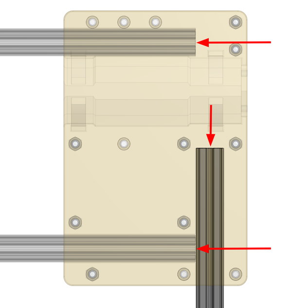
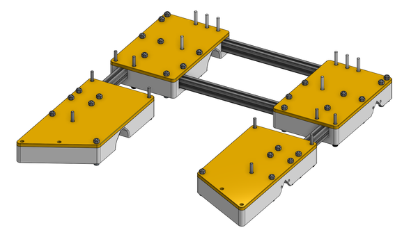
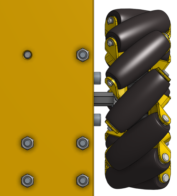
Start by grabbing 8 zip ties, the four 01_Chassis_Front/Back_Left/Right_Bottoms. Thread the zip ties through the holes on the bottom, without tightening them. The zip ties are fed through the marked rectangles in the image below and will help secure the motors later on.
After inserting the Zipties, gather 01_Chassis_Back_Right_Bottom, 01_Chassis_Back_Right_Top, 01_Chassis_Frame_Side, & both 01_Chassis_Frame_Fronts.
Place the extrusion into the clamshell portions, adding the 3D printed adapters if necessary, and butt the extrusion as far to the end as possible.
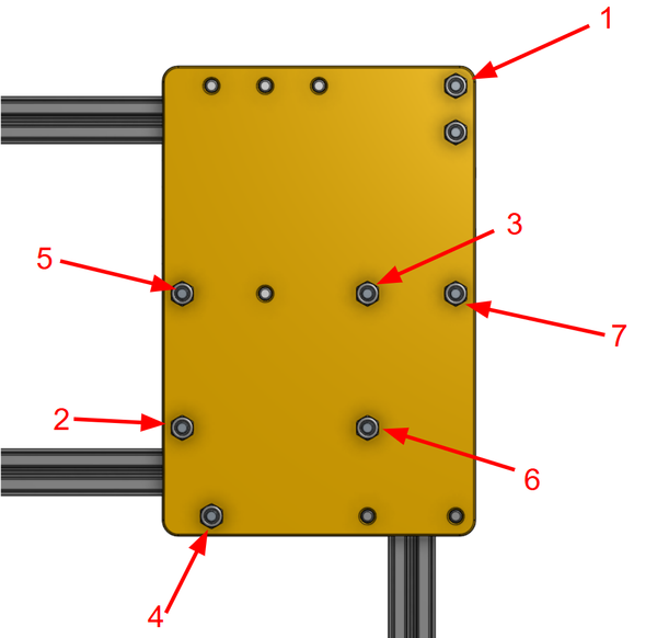
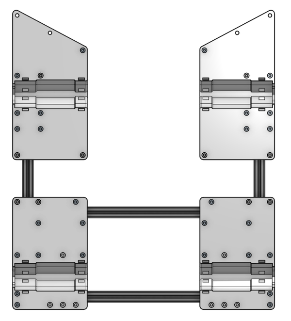
Align the top piece and clamp the clamshell down on the extrusion by adding the 35mm (1.375”) bolts and nuts. The bolts will have their heads on the bottom with nuts on the top. When clamping down ensure that the frame does not shift. It is best practice to leave all the bolts loosely tightened then finalizing the tightening in a star like pattern, see the final diagram for a loose idea of tightening order. Note that not all bolt holes need to be used.
Next add the 01_Chassis_Back_Left_Bottom and 01_Chassis_Front_Left_Bottom on the other side of the robot. Take 01_Chassis_Frame_Side and butt it up against the 3D printed part as was done previously. Then butt the two frame pieces from the previous clamshell against the extrusion. Add the 35mm (1.375”) bolts, again tightening in a vaguely star pattern, making sure that the extrusion does not shift.
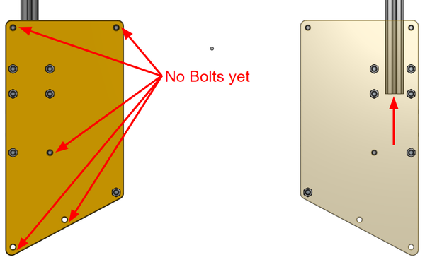
Next up are the front clamshells, which will go together the same with 3 key differences:
- There will not be a horizontal extrusion
- The innermost bolt holes surrounding the extrusion will be left empty
- The front should be a certain width and will be loose until Catapult/Intake assembly
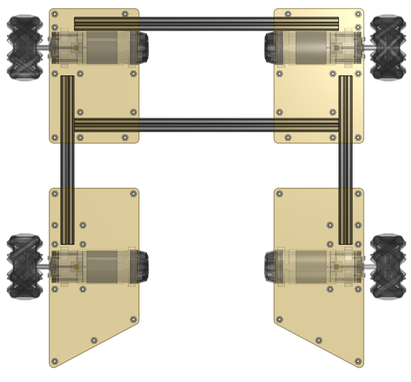
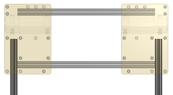
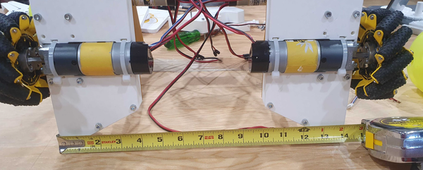
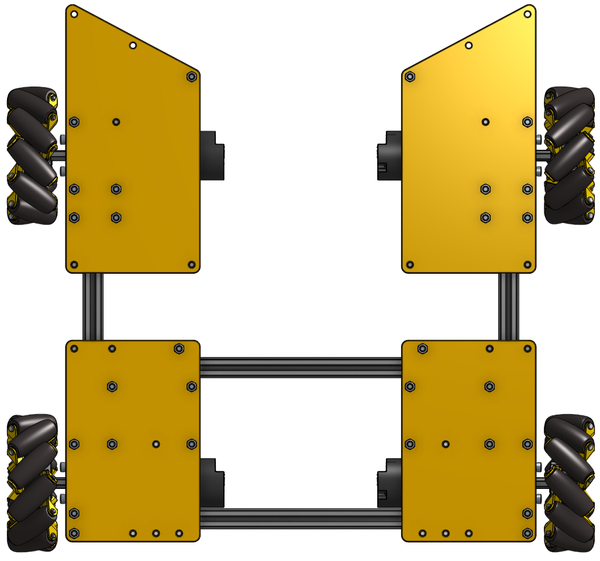
Now it is important to check the shape of the chassis. Because there is no front horizontal extrusion, the chassis can very easily bow inwards. Check, and readjust if necessary, that the outside edges of the front of the chassis measure to 14” (~356mm) before final tightening of all 35mm (1.375”) bolts. If the gap between the chassis pods are not large enough, the robot will struggle to intake Artifacts.
Attaching the Chassis Motor/Gearboxes
The Everybot chassis explicitly supports the following motor/gearboxes, which require the following bolts at our recommended lengths and add ratios:
- HD Hex Motor 20:1 Planetary Gearbox -> Qty(2) x M3 at 10mm
- Yellow Jacket Planetary Gear Motors 19.2:1 -> Qty(2) x M4 at 10mm
- NeveRest Orbital 20 Gearmotor -> Qty(2) x M3 at 10mm
Note that socket heads may make wheel mounting harder depending on the setup. Button head bolts may fix this issue.
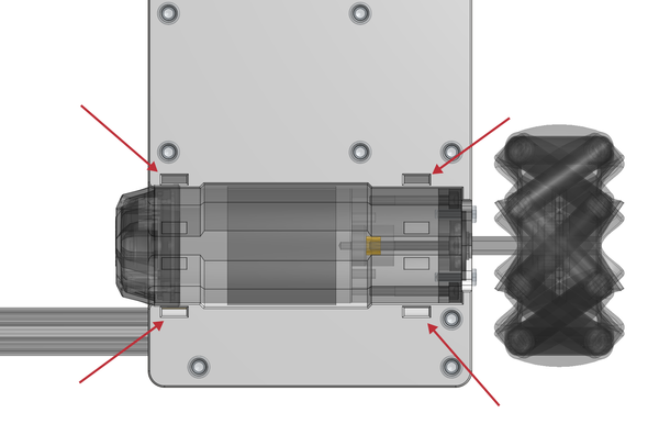
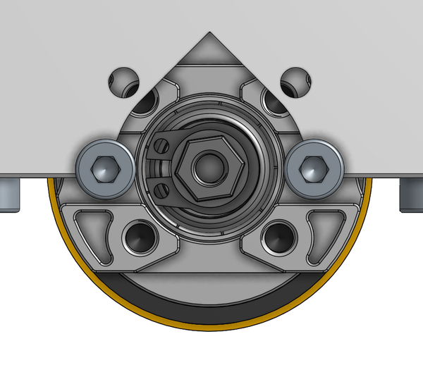
The HD Hex Motor and NeveRest Orbital 20 will be mounted with two exposed holes in the image below with the bolts listed above. The bolts will be 10mm long M3s for the HD Hex and the NeveRest.
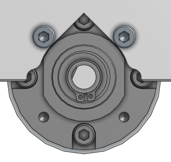
The Yellow Jacket Planetary requires a slightly different mount, using Two M4 bolts at 10mm.

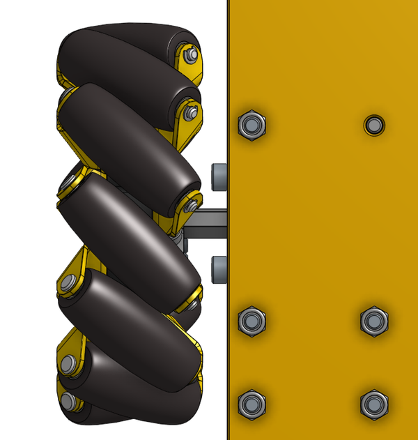
Adding Wheels
When adding your mecanum wheels you must keep in mind the skew of the wheels. You have wheels with left skew and wheels with a right skew.
Left Skew Right Skew
Please use the following skews for your mecanums, front left -> left, front right -> right, rear left -> right, rear right -> left.
Below is a matrix that maps a possible setup for a motor wheel combo. We have only tests cells where the vendors for wheel/motor match but we believe that a solution is possible if marked yes. We recommend CADing out different configs and not blindly following this chart.
| HD Hex Motor 20:1 Planetary Gearbox | Yellow Jacket Planetary Gear Motors | NeveRest Orbital 20 Gearmotor | |
| 75mm Mecanum Wheel Set | Yes, comes with the hubs | Yes, with a thru-sonic hub, let the boss face away from the wheel | Yes with a 6mm D nub |
| 104 mm GripForce Mecanum Wheel Set | Yes, with a hyper hub | Yes, with a Hyper Hub | Yes, with a hyper hub |
| BB Mecanum Wheels | Yes, use locking motion hub with nub config | Yes, with a thru-sonic hub, use the nub config and face the boss away | Yes with a 6mm D nub on the output and with the wheel’s nub config |
| HD Mecanum Wheels | Too wide | Too wide | Too Wide |